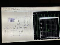
Replacing the output pair in JLH with a complementary pair and adding a pair of diodes in the offset , I got a conventional push - pull amplifier circuit with the following parameters

TND 0.52% at 5V amplitude.
By replacing the Q2 transistor with a composite one, it was possible to significantly improve these parameters without compromising the simplicity of the circuit.


And this is practically only the second harmonic. Quiescent current 0.87A
at 8V TND 0.0091%
That's what I wanted to introduce you to.
P.S.
The inscriptions on the diagram are for 4 ohms , the TND graph is already for 8 ohms 0.0044%

TND 0.52% at 5V amplitude.
By replacing the Q2 transistor with a composite one, it was possible to significantly improve these parameters without compromising the simplicity of the circuit.
And this is practically only the second harmonic. Quiescent current 0.87A
at 8V TND 0.0091%
That's what I wanted to introduce you to.
P.S.
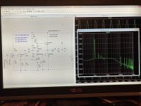
The inscriptions on the diagram are for 4 ohms , the TND graph is already for 8 ohms 0.0044%
Last edited:

I would be very grateful if you could give an example of these actions. I'm a weak user and it bothers me too.Those big caps in the sim are hiding your actual THD. If you replace the caps with DC voltage sources it should lower the FFT noise floor at lower frequencies so you don't have that line riding diagonally with frequency.
Sure. Could you attach the .asc to a post?I would be very grateful if you could give an example of these actions. I am a weak user
If I understood correctly, reducing C5 now does not accurately show the amplitude, but the noise shelf is better. TND got a little better too.Sure. Could you attach the .asc to a post?
Attachments
Yep, that's the idea. Changing the cap size messes up the amplitude, but if you insert a DC Voltage source (like you have for your power supply) in place of the output cap, you should keep your correct output amplitude and the better noise floor. Check the DC voltage level of your output point on the amp side of the cap, and make the DC source equal to that number. Connect positive to amp output, negative to load resistor.If I understood correctly, reducing C5 now does not accurately show the amplitude, but the noise shelf is better. TND got a little better too.
Yep, that's the idea. Changing the cap size messes up the amplitude, but if you insert a DC Voltage source (like you have for your power supply) in place of the output cap, you should keep your correct output amplitude and the better noise floor. Check the DC voltage level of your output point on the amp side of the cap, and make the DC source equal to that number. Connect positive to amp output, negative to load resistor.
it doesn't work that way, or I didn't understand. 🙂
Attachments
Well, thanks! Only it won 't work out quickly , I 'm writing from my phone , communication with the computer via mail , while I do it ... I will immediately unsubscribe. About an hour, no less.
It turned out faster 🙂 Yes, thank you, I understand your idea. At high levels, it seems that you need to additionally edit these sources. Now it is easier to consider the forest of harmonics. 🙂. And edit. Although in general for a 5-transistor amplifier, this is very, very good, TND 0.0082% at 8V amplitude. Moreover, at 8 ohms it will be twice as good as 0.0037%. I'm thinking of collecting for myself. Everything for this is already ready , except the amplifier itself . I don't know your name. Very grateful. That was a problem.

I have a case from Quad 405, it remains to understand what kind of board to make for this. The corner for transistors in it does not inspire confidence. I will think.
It is also interesting whether it is necessary to use a stabilizer for an amplifier, or a simple bridge or repeater will suffice. From the point of view of its own noise.
It is also interesting whether it is necessary to use a stabilizer for an amplifier, or a simple bridge or repeater will suffice. From the point of view of its own noise.
Last edited:
Don't forget the emitter resistors in the output stage. These are needed for thermal stability.
You will not see that in LTspice unless you also simulate thermal effects and temperature changes.
But in the real amp you surely need them.
The diodes D1 and D2 should be replaced by a Vbe multiplier which can track the temperature of the output devices to avoid thermal runaway and releasing the magic smoke ;-) .
Jan
Happy to help ☺️ My name is Pat. And listen to @jan.didden, who has probably forgotten more than I know about amps.It turned out faster 🙂 Yes, thank you, I understand your idea. At high levels, it seems that you need to additionally edit these sources. Now it is easier to consider the forest of harmonics. 🙂. And edit. Although in general for a 5-transistor amplifier, this is very, very good, TND 0.0082% at 8V amplitude. Moreover, at 8 ohms it will be twice as good as 0.0037%. I'm thinking of collecting for myself. Everything for this is already ready , except the amplifier itself . I don't know your name. Very grateful. That was a problem.View attachment 1099087
Thanks Jan ! I've heard a lot of good things about you. You are an excellent specialist. 👍 I have no experience in thermal packages. Resistors 0.15-0.22 Ohms are provided. We still need to check how they will affect, because the transistor will be covered. Diodes are taken for simplicity, they can be placed on the radiator. I don't know which is better, diodes or a Vbe multiplier. All additions are welcome, as are studies. If you have the time. I'm 61 , I'm an old radio engineer 🙂. Hi Pat , very nice! I have the same problems with memory 🙂
I forgot a lot of what I knew.
. But I love new things in radio and other industries.
I forgot a lot of what I knew.
. But I love new things in radio and other industries.
Last edited:
🙂 You have a great sense of humor, maybe I'll be the same when I grow up.
I have a question for you . What determines the frequency at which the phase characteristic of the amplifier passes through 0. In this amplifier and similar ones , it is in the region of 2-3 kHz , and in amplifiers with a diff pair of about 200-300 Hz .
With resistors 0.22, TND decreased from 0.008 to 0.005. %. Can be set.
Last edited:
I was slightly mistaken. With resistors 0.22, TND decreased from 0.008 to 0.005. % Can be set. for 8 ohm load. For 4 Ohm , it got worse from 0.008 to 0.025 %. ? It is necessary to add 19 ohms to the offset and reduce the output amplitude to 7 V for 0.007% TND ,and lose 2 watts of power.
Last edited:
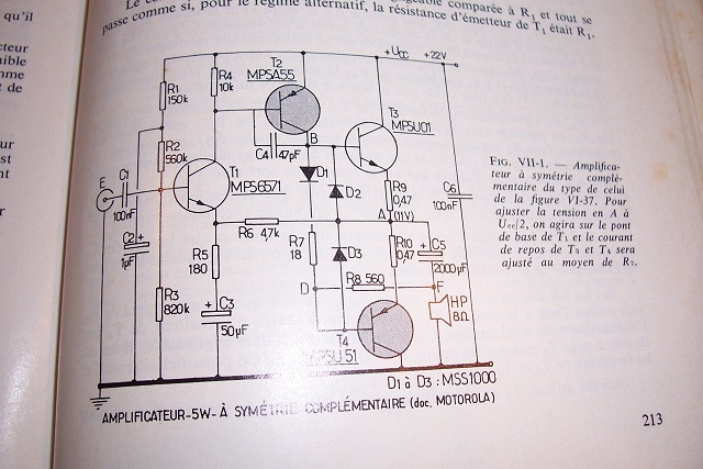
This topology has little in common with JLH. It a dead-ringer of early Motorola application notes examples. This one is inverted, but it is fundamentally identical:
Many other examples can be found here:
https://www.diyaudio.com/community/...wer-amplifiers-for-daniel.335079/post-5724404]
A more modern example can be found here:
https://www.diyaudio.com/community/...ifiers-with-a-new-twist-1.337017/post-5768643
Many other examples can be found here:
https://www.diyaudio.com/community/...wer-amplifiers-for-daniel.335079/post-5724404]
A more modern example can be found here:
https://www.diyaudio.com/community/...ifiers-with-a-new-twist-1.337017/post-5768643
You really cannot trust the LTspice THD numbers to that accuracy, not even whether they increase or decrease.
Most transistor models do not model the non-linearities with any accuracy.
You need to build it and measure ;-)
Jan
Most transistor models do not model the non-linearities with any accuracy.
You need to build it and measure ;-)
Jan
Thanks for the links, Elvee
That's what I wrote at the beginning :
Replacing the output pair in JLH with a complementary pair and adding a pair of diodes in the offset , I got the usual circuit.
You're right here Jan, I just wanted to go the civilized way 🙂
That's what I wrote at the beginning :
Replacing the output pair in JLH with a complementary pair and adding a pair of diodes in the offset , I got the usual circuit.
You're right here Jan, I just wanted to go the civilized way 🙂
Last edited:
- Home
- Amplifiers
- Solid State
- New simple amplifier