Firstly, a cap will pass AC but block DC, so what that does in this case is remove offset from the input you are feeding the chip. I am not a LM3886 expert, but i believe the chip itself has some base DC offset, so removing any additional DC from the signal input is recommended to keep output DC low. The value of the cap depends on the circuit you are using, but you are basically building a low-pass filter with a parallel R (in this case Q1 i guess), so you have to calculate the exact values to use based on the circuit in question. You can look here for more info: https://www.circuitbasics.com/desig...Low-Frequency-Cutoff-at-the-Amplifier's-Input
If you plan to build the circuit above i guess you could just use the stated values, otherwise look around here, there are a whole bunch of LM3886 circuits that will do it for you.
If you plan to build the circuit above i guess you could just use the stated values, otherwise look around here, there are a whole bunch of LM3886 circuits that will do it for you.

Resistor Ra is the load seen by the input C. This creates a first order high pass filter. You can use an online calculator to determine where the -3dB point is for this high pass filter. 10u over 100k is fine.
Why bother with an online calculator? Just commit fc = 1/(2*pi*R*C) to memory and use a regular calculator. Fc is the -3 dB point. That along with Ohm's Law are the equations I use the most.
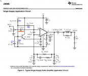
There are several RAs in the circuit. Also several CAs just for the sake of confusion. I've labeled some of them in attached schematic.
At DC, the input impedance is Rin = R3+R1||R2. That works out to 75+(100*91)/(100+91) = 123 kΩ. At frequencies where the reactance of C1 is significantly lower than the resistance of R1||R2, the input impedance drops to 75 kΩ.
If you want negligible impact of the input cap, design such that it sets a pole at 2 Hz (10x below 20 Hz - the lower end of the audio band). So we get back to fc = 1(2*pi*R*C), but this time we want to find C. Rearranging: C = 1/(2*pi*R*fc) -> C = 1/(2*pi*75000*2) for a 2 Hz cutoff -> C = 1.06 uF. Round up to the nearest standard value: C = 2.2 uF. C = 1.0 uF will probably be OK as C1 hasn't quite "kicked in" yet, so the input impedance is higher than 75 kΩ.
For the exact frequency response, run a simulation. Or build the circuit and measure it. 🙂
Tom
Attachments
Because it is faster & easier & fool proof and where is my bloody calculator, I haven't seen that thing in ages.Why bother with an online calculator?
1 does not want ac blocker on the input, as music is ac, amp would be silent.as above. (in the schematic below, it's the 10uF highlighted in orange)
Thanks for the reply.
View attachment 1094280
Cap prevents dc to enter amp and be amplified and heat or displace or burn the voice coil. And with amps input impedance cap presents high pass filter.
Some amp designers calculate cap value for 2Hz, to be flat from 20Hz. That may be excessive.
But 1 can use the cap value as advantage in high pass filter for biamplified system. To lower the im distortion and other advantages.
1 can do a lot.
It's in your phone, look, over there ;-)Because it is faster & easier & fool proof and where is my bloody calculator, I haven't seen that thing in ages.
found 5 pieces of National (before they were bought) in my stash. bought 4 more (used though but don't think that matters) for the price of postage just today. 😀1 must obtain lm3886 which is not fake 1st
also found 5 pieces of LM4780! 😀
Yep. I use an HP48 emulator on my iThingy. Works great. I also use a handful of HP48G that I picked up on eBay for dimes on the dollar and some other HP calculator that I bought on the used market locally. Must ... have ... RPN...It's in your phone, look, over there ;-)
Tom
10uF with 75k ohm, HPF is at 0.21Hz.
Any combination of values getting less than 2Hz is very good.
Any combination of values getting less than 2Hz is very good.
im building the p3a and have a similar question, today i tested 20 different potential candidates for p3a input capacitor, all are tested under equal circumstances, at 22k load, 3 volt peak to peak which is close to two volt rms
how to interprete theese screen dumps, which are the good the bad and the ugly,
list is from low uf value to high.
1, Rifa PHE450 100nf 2000v
2, K73-11 0,82uf 400v
3, K73-16 1uf 400v
4, Roederstein MKP1839 1uf 400v
5, Phillips MKT 1,2uf 250v
6, Vishay MKP1845 2uf 160v
7, K71-11 2,2uf 250v
8, Siemens silver stacked 2,2uf 250v
9, Rifa PHE 840E 2,2uf 300v
10, Roederstein 1860 2,2uf250v
11, K73-16 3uf 400v
12, Orange drop Phillips 4,7uf 100v
13, Roederstein MKC 1860 5,6uf 250v
14, K73-11 5,6uf160v
15, Roederstein 1813 6uf 100v
16, Red Wima 6,8uf 50v
17, K73-11 6,8uf 160v
18, Roederstein MKT1813 10uf 250v
19, Bipolar green muse 22uf 50v
20, Iskra KNG1914 200uf 1000v Dc link capacitor


 View attachment 8, Siemens silver stacked 2,2uf 250v.png


 View attachment 15, Roederstein 1813 6uf 100v.png


 View attachment 20,Iskra KNG1914 200uf 1000v polypropylene.png
how to interprete theese screen dumps, which are the good the bad and the ugly,
list is from low uf value to high.
1, Rifa PHE450 100nf 2000v
2, K73-11 0,82uf 400v
3, K73-16 1uf 400v
4, Roederstein MKP1839 1uf 400v
5, Phillips MKT 1,2uf 250v
6, Vishay MKP1845 2uf 160v
7, K71-11 2,2uf 250v
8, Siemens silver stacked 2,2uf 250v
9, Rifa PHE 840E 2,2uf 300v
10, Roederstein 1860 2,2uf250v
11, K73-16 3uf 400v
12, Orange drop Phillips 4,7uf 100v
13, Roederstein MKC 1860 5,6uf 250v
14, K73-11 5,6uf160v
15, Roederstein 1813 6uf 100v
16, Red Wima 6,8uf 50v
17, K73-11 6,8uf 160v
18, Roederstein MKT1813 10uf 250v
19, Bipolar green muse 22uf 50v
20, Iskra KNG1914 200uf 1000v Dc link capacitor
Hi sadface.. the data is nice, if it isn't flawed, and this date is flawed, look at the roll off in low frequency, I accidentally pushed the x10 to x1on my probe, so I'm sorry to say readings are useless, but I will today do them over, at correct setting, for those interested.
- Home
- Amplifiers
- Chip Amps
- how does 1 choose the input capacitor value (AC blocker?) that's in the LM3886 (and maybe others) schematics/datasheet?