Hi,
Got a Denon DRA-1025RA on the bench. It plays, but since I got it I noticed that the stereo separation is lousy. It has a "mono" button and "Simulated stereo" which I thought may be the problem, but noticed that the bass control does not work at all.
Disassembled it to find the bass control is physically broken. The nut that holds it to the chassis was not tight and I guess over the years it snapped guts.
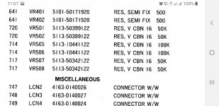
VR402, part number stamped on it is 2110536006, and 30KCX2.
Service manual has an additional number of V1620V30FC303K with a description of 30Kohms BASS.
Any idea where I can find a replacement?
For now, I may just put two (well, four) 15K fixed resistors in there to simulate being in the center of the range.
Thanks!
Got a Denon DRA-1025RA on the bench. It plays, but since I got it I noticed that the stereo separation is lousy. It has a "mono" button and "Simulated stereo" which I thought may be the problem, but noticed that the bass control does not work at all.
Disassembled it to find the bass control is physically broken. The nut that holds it to the chassis was not tight and I guess over the years it snapped guts.
VR402, part number stamped on it is 2110536006, and 30KCX2.
Service manual has an additional number of V1620V30FC303K with a description of 30Kohms BASS.
Any idea where I can find a replacement?
For now, I may just put two (well, four) 15K fixed resistors in there to simulate being in the center of the range.
Thanks!
Also note that none of the fixed values around it are symmetric. 11k to 1.8k, 0.15u to 1u, 1.3k to 180r. 6:1 to 7:1 differences. I would bet on a 20% audio. Or 24k and 6k "centered".not a linear pot
fixed resistors
Disconnect CN6F: connect pin 1 to 6 and pin 3 to 4 at the "other side". Done. Remove all tone control stuff and knobs. Make a nice rectangular (nonferro metal) label with brandname, family name or the like and glue it over the holes in the front cover. Solved.
BTW the thread title says DRA-1024RA but I think it is a DRA-1025RA?!
BTW the thread title says DRA-1024RA but I think it is a DRA-1025RA?!
Last edited:
If it's not a linear pot the center won't be 15K/15K. Me thinks the C is the taper.
Craig
Sorry, what does "C" stand for?
Also note that none of the fixed values around it are symmetric. 11k to 1.8k, 0.15u to 1u, 1.3k to 180r. 6:1 to 7:1 differences. I would bet on a 20% audio. Or 24k and 6k "centered".
Yup. Using a meter, the "center" is about 5K/25K. so, for sure not linear. I guess it is audio taper?
I already reassembled it with the 15K/15K. I guess the Bass will be a little low until I figure out how I want to fix it permanently.
Disconnect CN6F: connect pin 1 to 6 and pin 3 to 4 at the "other side". Done. Remove all tone control stuff and knobs. Make a nice rectangular (nonferro metal) label with brandname, family name or the like and glue it over the holes in the front cover. Solved.
BTW the thread title says DRA-1024RA but I think it is a DRA-1025RA?!
Interesting solution. May go this route too. I generally leave the tone controls in the center anyway. However, I am a bit OCD with having things "correct", so I am going to keep looking for a replacement part (or a way to fix this one).
I have the old one disassembled, and was thinking if I can find a similar part, I should be able to swap the fiberboard with the ink.
Yeah, sorry! 1025RA.
Hmm. I wonder if I can fix this one. Super glue on the fiberboard, then some conductive glue on the crack.
https://www.amazon.com/Conductive-Electrically-Adhesives-Conduction-Connectors/dp/B09KVK5NB3
https://www.amazon.com/Conductive-Electrically-Adhesives-Conduction-Connectors/dp/B09KVK5NB3
Yup. Using a meter, the "center" is about 5K/25K. so, for sure not linear. I guess it is audio taper?
I would bet on a 20% audio.

Well, I tried the glue/conductive paint route and it worked for a bit- then I lost once channel. So, I guess that is not going to be a permanent fix.
I could go back to fixed resistors, or bypass the entire "tone" circuit- but I'd really like to keep it correct. I could also look for a broken receiver for parts, but that may be just getting lucky.
I think this is what most call a 16MM pot? I have done a lot of searching for anything similar but it seems that 30K is not standard, and alps wants minimum 1000 quantity to even talk to me! Mouser, and the likes seem to have 10K. I have seen some sites with 50K and 100K. My thought was to try and modify the circuit to operate the same with the alternate value. How practical is that?
Neither is 33k an usual potentiometer value nor is paralleling feasible as he'd need a quadruple potentiometer in this case. I'd try a 2 x 47k audio taper potentiometer first. Just to be pedantic, this could be paralleled with a 91k/22k or 100k/10k voltage divider per pot to approach the original 33k value. Or just follow jean-paul's advice with some slight modification in order to compensate for the network damping.
Best regards!
Best regards!
Cx stands for antilog potentiometer.Most probably that tone network is found in the feedback path of an amplifier . You can simulate a log one with a linear one and use ESP tricks: https://sound-au.com/project01.htm#s7
I guess if it were in the NFB path, i. e. a Baxandall tone stack, the potentiometer characteristics were linear and the surrounding components were of the same values at both sides.
Best regards!
Best regards!
They all use antilog cx pots.Log pots can be used, but they will work in reverse...turning down anticlockwise to increase the bass or highs...
Attachments
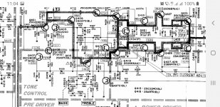
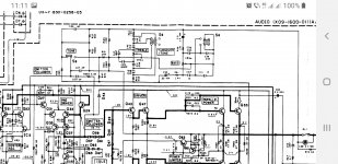
Yes, you're right. I had a look into the service manual. The tone stack is in a NFB path, without being a Baxandall one. In the DRA-1035 it is in parallel with another NFB network of the opamps in IC402. Quite some unusual solution, I think. Anyway, the unit should even work with the tone control network unplugged (CN6F connector disengaged).
Best regards!
Best regards!

Yes if a tone defeat switch is provided .If it is not, there's a chance to turn the amplifier into an oscillator...Anyway, the unit should even work with the tone control network unplugged (CN6F connector disengaged).
Best regards!
That amplifier will possibly improve without the tone control circuit (in the NFB loop, bah). So more "correct" than it was before. Mediocre potentiometers and added part tolerances don't make the world better. Many don't use these, it were features to keep up with the competition and thus for better sales. Not many would then have bought an amplifier with for instance just 1 input, no tone control, no speaker A/B switches etc. Most had a cassettedeck, tuner, CD player. Today we see the contrary with Chi-Fi amplifiers and 1 digital source playing web radio, FLAC files, TV sound via Toslink etc. The less there is the less can break down.
The search for parts probably long out of production, find them and then pay too much, then install them and never use them is also not correct 🙂
The search for parts probably long out of production, find them and then pay too much, then install them and never use them is also not correct 🙂
Last edited:
Very good point..The search for parts probably long out of production, find them and then pay too much, then install them and never use them is also not correct 🙂
Better read the reviews before sharing impressions on an amplifier you don't have...
https://www.hifiengine.com/manual_library/denon/dra-1025r.shtml
https://www.hifiengine.com/manual_library/denon/dra-1025r.shtml
- Home
- Amplifiers
- Solid State
- Denon DRA-1024RA repair