Hi! When I use dc heater supplies (say in phono stages) I usually elevate the heaters above cathode potential. As I understand it there can't be a flow of electrons from the heaters at a potential positive to the cathode and no potential hum couples from the heaters into the signal. But what happens now is that the signal on the cathode couples into the heaters, right? Or does the cathode resistor bypass C provide a lower impedance path to ground and this wouldn't happen?
And if it happened could it be an issue of some kind? Say e.g. in a stereo amplifier with parallel wired heaters would it have a negative influence on channel separation?
Thank you for your thoughts and maybe even experiences.
And if it happened could it be an issue of some kind? Say e.g. in a stereo amplifier with parallel wired heaters would it have a negative influence on channel separation?
Thank you for your thoughts and maybe even experiences.

Elevating the heaters is a bit overmystification. If the heater is at about the same DC level as the cathode, there is no current from heater to cathode. It has even less influence at DC heating.
I simply connect one end of the DC heating voltage to signal ground. Even if the cathode is at B+/2 like in a cascode, I haven't experienced any problem. I know the datasheet specifies the maximum heater-cathode voltage, but no issue so far (E88CC, 300V B+).
I simply connect one end of the DC heating voltage to signal ground. Even if the cathode is at B+/2 like in a cascode, I haven't experienced any problem. I know the datasheet specifies the maximum heater-cathode voltage, but no issue so far (E88CC, 300V B+).
Ancient discussion on the subject here: https://www.diyaudio.com/community/...ament-current-better-way-to-build-amps.88262/
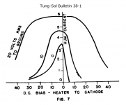
I can't find in my files the Tung Sol 38-1 paper cited but did keep a copy of the graph below.
I can't find in my files the Tung Sol 38-1 paper cited but did keep a copy of the graph below.
Attachments
Member
Joined 2009
Paid Member
fascinating.
I was particularly interested to read that "Heaters should not be operated above rated voltage, as hum doubles with a 6% increase in heater voltage". Leaves me wondering if hum halves for a 6% reduction in heater voltage.
Anyhow, what we already knew "Hum can be reduced to a negligible value by use of sufficient bias between heater and cathode to prevent the net voltage reversing."
If there is any leakage current from cathode to filament . . .
If that tube is used as a concertina phase splitter, Then the push and pull signal amplitudes will be un-equal, even though the Rk and Rp resistors are perfectly matched.
The above is true for AC powered filaments.
The above is true for DC powered filaments.
Concertina users take note.
If that tube is used as a concertina phase splitter, Then the push and pull signal amplitudes will be un-equal, even though the Rk and Rp resistors are perfectly matched.
The above is true for AC powered filaments.
The above is true for DC powered filaments.
Concertina users take note.
The E88CC has a rather high heater-cathode voltage rating if I remember well.I simply connect one end of the DC heating voltage to signal ground. Even if the cathode is at B+/2 like in a cascode, I haven't experienced any problem. I know the datasheet specifies the maximum heater-cathode voltage, but no issue so far (E88CC, 300V B+).
Anyway, heater-cathode breakdown is a long-term effect. It has something to do with electrolysis of the insulator, see Philips Technical Review December 1956.
Last edited:
rdf, thanks so much for linking to the January 1938 tung-sol document as I hadn't seen it referenced before.
The following link has a section on heater-cathode leakage where I've tried to collate relevant info: https://www.dalmura.com.au/static/Hum article.pdf
The earliest reference to measuring heater-cathode resistance was by Klemperer from Westinghouse in Sept 1936, so plausible that the topic was of interest at the time and Tung-Sol engineer was bouncing off Klemperer's publication.
https://worldradiohistory.com/Archi...-Review/50s/Philips-Technical-Review-1956.pdfsee Philips Technical Review December 1956
pages 184+ in the PDF (19MB), note page 191
The scans of the Philips Technical Review series on the World Radio History site originate from a personal page on a Philips site but at some point the series was taken off line.
That former Philips page also contained a usefull Excel index of the Philips Technical Review series, together with some other Philips publications, again with usefull Excel indexes. I downloaded them all at the time. They can now be found here:
Philips Technical Review 1936 - 1988 Index
Philips Research Reports 1946 - 1977
Philips Research Reports Supplements 1961 - 1977
A link to the Philips Technical Review series on the World Radio History site:
Philips Technical Review 1936 - 1989
There is an article titled "Save those 7199s!"
It appeared in Sound Practices Issue 10, page 35.
It tells the reason for the 7199 failure in Dyna ST70 (not dead, but causing distortion, etc.).
It gives a circuit modification to prevent the 7199 failure (If you can find a NOS 7199 to replace the one that is already failed).
Hint: The filament to cathode of the 7199 triode concertina is what 'fails'.
See this on valve heaters:
https://www.valvewizard.co.uk/heate...elevation voltage can be,30 to 60V is typical.
https://www.valvewizard.co.uk/heate...elevation voltage can be,30 to 60V is typical.
- Home
- Amplifiers
- Tubes / Valves
- Elevated heaters - coupling from cathodes into heater supply?