I have been playing with the 6SJ7 tube to see if it can handle a 100k load, and it seemed to be able to do it well. I did the bandwidth sweep and did not see any attenuation in the audible range. The B+ was 300V, the plate resistor was 47k, and the screen was set at 75V with Zener diode. I had a 1k potentiometer with a 100 Ohm resistor in series on the cathode as such:

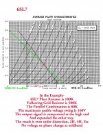
With 75V on the screen, the 47k DC load line went right through the knee of the curve. I noticed the 1k sine wave had the characteristic 2nd order distortion with flattened bottom curve and peaked upper curve when I biased the tube to get a plate voltage of 150V. When I turned the cathode pot down, at 150 Ohm of total resistance, the sine waves evened out and became nice and symmetrical. The plate voltage was around 90V. The input signal was 2V p-p. Output level across the 100k load was about 120V p-p. The upper and lower peaks didn't look flattened, but I can't tell for sure. I have a very rudimentary scope so I can't export the waveform or do FFT. I tried it with a bunch of different tubes and had the same results. It looked like the 6SJ7 likes about 4.5mA. Can someone with proper gears check the circuit and see how much distortion there is? Thanks.
With 75V on the screen, the 47k DC load line went right through the knee of the curve. I noticed the 1k sine wave had the characteristic 2nd order distortion with flattened bottom curve and peaked upper curve when I biased the tube to get a plate voltage of 150V. When I turned the cathode pot down, at 150 Ohm of total resistance, the sine waves evened out and became nice and symmetrical. The plate voltage was around 90V. The input signal was 2V p-p. Output level across the 100k load was about 120V p-p. The upper and lower peaks didn't look flattened, but I can't tell for sure. I have a very rudimentary scope so I can't export the waveform or do FFT. I tried it with a bunch of different tubes and had the same results. It looked like the 6SJ7 likes about 4.5mA. Can someone with proper gears check the circuit and see how much distortion there is? Thanks.
Last edited:
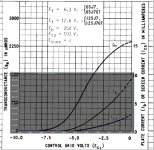
6SJ7, same as most tubes, likes any ample current. "Ample" depending on supply, load, and THD criteria. It can't be very fussy, because US broadcasters used the 6J7/6SJ7 for EVERYTHING under a part-Watt. (Even for triode. The 6J5 was very much a 6J7, but for broadcasters it was simpler to just keep the pentode in spares-stock.)like the 6SJ7 likes about 4.5mA
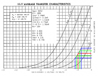
The amplifier tables are good authority.see if it can handle a 100k load

6SJ7 will drive 100K very well. Without the extra mA or the Zener.
Well there you go! Thanks man. My copy of the RCA manual (RC-30) only has 2 lines about the 6SJ7, and none of the data sheets that I can find gave operating conditions.
I was surprised it wasn't in RC20, had to find RC17. Most of the important issues are online one place or another.My copy of the RCA manual (RC-30)
You can use REW, https://www.roomeqwizard.com/
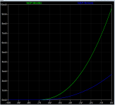
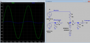
It's spectrum analayser funtion not only display FFT abut also the distortion. You need only to make suitable adapter from the output to line input of sound card. Here I give you my sim prediction.
It's spectrum analayser funtion not only display FFT abut also the distortion. You need only to make suitable adapter from the output to line input of sound card. Here I give you my sim prediction.
Attachments
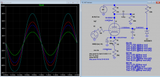
Thanks! That's great. Definitely needs an attenuator. Probably don't want to be feeding 120V p-p into my sound card😛You can use REW, https://www.roomeqwizard.com/
It's spectrum analayser funtion not only display FFT abut also the distortion. You need only to make suitable adapter from the output to line input of sound card. Here I give you my sim prediction.
You will have to also check next stage's capacitance, if this is used as a driver for the output stage.
This is my version of line input attenuator for power and line preamp. The output level will be limited as clamped by zeners to about 1.2Vp accepted by line input, DC blocking capacitor is used to avoid passing DC. Some sound cards (in the low end PC) has phantom spectrum even without input so be aware.
Attachments
Last edited:
Installed REW, got everything hooked up. First checked the signal generator and the sound input device. Harmonic distortion was less than 0.005% across the board, so everything was good. 300V supply. For the setups without the Zener shunt, the screen was bypassed to the cathode with a 0.47uF cap.
The last three were done with a pot on the screen and a pot on the cathode. The 6th and the 7th ones were tweaked for the lowest THD. The last one I hooked up to a 6AV5GA, UL with cathode feedback at 60mA and tweaked the pots until it sounded the best.
| Rp | Rk | Rs | THD % | 2nd | 3rd | 4th | 5th |
| 47k | 150R | 120k, 75V Zener | 2.71 | 1.47 | 2.17 | 0.68 | 0.11 |
| 100K | 500R | 120k, 75V Zener | 12 | 9.24 | 7.45 | 0.69 | 1.13 |
| 100k | 500R | 330k (67V) | 5.68 | 4.30 | 3.36 | 1.42 | 0.60 |
| 100K | 500R | 270k (75V) | 6.59 | 1.94 | 5.96 | 1.92 | 0.17 |
| 100K | 500R | 470k (52V) | 9.83 | 9.64 | 1.77 | 0.73 | 0.33 |
| 39k | 137R | 120k (90V) | 2.13 | 1.01 | 1.74 | 0.66 | 0.18 |
| 47k | 498R | 101k (135V) | 2.05 | 0.78 | 1.77 | 0.65 | 0.20 |
| 47k | 477R | 143k (113V) | 4.00 | 3.97 | 0.50 | 0.094 | 0.064 |
The last three were done with a pot on the screen and a pot on the cathode. The 6th and the 7th ones were tweaked for the lowest THD. The last one I hooked up to a 6AV5GA, UL with cathode feedback at 60mA and tweaked the pots until it sounded the best.

Oops, forgot to say that all the measurements were done at 1kHz, 2V p-p input. The outputs were all >100V p-p. The last one I had set with music at a reasonable volume and then ran through the test signal.
This is an interesting thread, I'm planning to do similar measurements using a PC86, my simulations look too god to be true!
Confirming that high order harmonic distortion are harmful to sound, and one must look beyond THD. Interesting numbers, thanks for sharing.Oops, forgot to say that all the measurements were done at 1kHz, 2V p-p input. The outputs were all >100V p-p. The last one I had set with music at a reasonable volume and then ran through the test signal.
Put 100 pF at the output, than do the BW sweep again.I did the bandwidth sweep and did not see any attenuation in the audible range.
100 pf is about what a 2A3 grid & stray C for the wiring adds up to. 👍

Put 100 pF at the output, than do the BW sweep again.
100 pf is about what a 2A3 grid & stray C for the wiring adds up to. 👍
The 6AV5 was for testing only. I have something much more nefarious planned. We're looking at a grid capacitance 1/10th of above.
frank.pocnet.netMost of the important issues are online one place or another.
Post #10 is a nice data set. But no mention of output voltage
signal level other than >100V p-p. Am I missing something??
For sake of comparison all tests of a series are usually run at
the same level, say 100v p-p.
These results are similar to what I got in another thread
where I used a plate load of 75K.
signal level other than >100V p-p. Am I missing something??
For sake of comparison all tests of a series are usually run at
the same level, say 100v p-p.
These results are similar to what I got in another thread
where I used a plate load of 75K.
Last edited:
#11:Post #10 ...... Am I missing something??
Since gain is not reported, still not a complete report. I am also curious what load it was driving; a truly un-loaded amplifier can be low distortion (tho most amps load themselves some).all the measurements were done at 1kHz, 2V p-p input. The outputs were all >100V p-p.
The AC Load vs the DC Load on the driver plate is always a concern, especially at higher levels.
The difference needs to be small as possible. Something to be careful of when driving a fixed
bias power tube. And always increases D%.
The difference needs to be small as possible. Something to be careful of when driving a fixed
bias power tube. And always increases D%.
Attachments
- Home
- Amplifiers
- Tubes / Valves
- 6SJ7 Distortion Level