Ich habe einen Mark Levinson Ml23 Verstärker und habe folgendes Problem! Ich kann den Ruhestrom auf dem linken Kanal nicht einstellen! Poti ist
ok ! Ruhestrom ca. 13mV und die Kühlrippen sind eher kühl. Am rechten Kanal habe ich 11mV eingestellt und ist lauwarm.
DANKE für die Hilfe!
Andreas
ok ! Ruhestrom ca. 13mV und die Kühlrippen sind eher kühl. Am rechten Kanal habe ich 11mV eingestellt und ist lauwarm.
DANKE für die Hilfe!
Andreas
Last edited:

English please.
I have a Mark Levinson Ml23 amplifier and have the following problem! I can't adjust the quiescent current on the left channel! Poti is
ok ! Quiescent current about 13mV and the cooling fins are rather cool. On the right channel I have set 11mV and is lukewarm.
THANK YOU for the help!
Andreas
A few questions:Ich habe einen Mark Levinson Ml23 Verstärker und habe folgendes Problem! Ich kann den Ruhestrom auf dem linken Kanal nicht einstellen! Poti ist
ok ! Ruhestrom ca. 13mV und die Kühlrippen sind eher kühl. Am rechten Kanal habe ich 11mV eingestellt und ist lauwarm.
DANKE für die Hilfe!
Andreas
1) what do you mean with 13mV current ?
2) how do you know you are turning the right pot
3) is the channel still able to produce music ?
Hans
According to the circuit diagram, the quiescent current should be 10mV to 12mV. There is only one trimming potentiometer per channel. The amp works perfectly!
Current should be in Amp and not in Volt.
In case of the ML23, quiescent current should be 275mA.
Show us the circuit diagram that you refer to that shows 10 to 12mV, but I´m afraid this concerns output offset voltage, which has nothing to with quiescent current.
Heatsinks remaining cold however are a good sign that quiescent current is too low, they must be ca 40 degrees.
Hans

The output is driven through two 0.1R resistors as you can see in the circuit diagram.
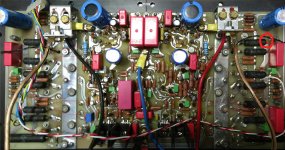
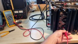
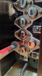
Without having to take your Amp apart, you can measure the voltage between the positive LS output on the outside and the red point on the PCB that I have indicated in the picture.
In this way you get the voltage over one 0.1R resistor which in the case of 275mA quiescent current should be 27.5mV.
Succes,
Hans
Attachments
That is, measuring device on the resistance and on the speaker output in the positive line?
Actually, I swapped all the electrolytic capacitors on the ML and re-soldered all the circuit boards!
And then what is the 10-12mV voltage for?
As I said, I can adjust the voltage with the trimming potentiometer on the right channel but not on the left channel?
Actually, I swapped all the electrolytic capacitors on the ML and re-soldered all the circuit boards!
And then what is the 10-12mV voltage for?
As I said, I can adjust the voltage with the trimming potentiometer on the right channel but not on the left channel?
What voltage can’t you trim, I asked you before because I don’t know what and where you are measuring.That is, measuring device on the resistance and on the speaker output in the positive line?
Actually, I swapped all the electrolytic capacitors on the ML and re-soldered all the circuit boards!
And then what is the 10-12mV voltage for?
As I said, I can adjust the voltage with the trimming potentiometer on the right channel but not on the left channel?
Hans
I suspect hes trying to measure and adjust the voltage across the 0.22 ohm emitter resistors that is shown as "je 10-12mv".
Yes, you are right.I suspect hes trying to measure and adjust the voltage across the 0.22 ohm emitter resistors that is shown as "je 10-12mv".
But measuring one emitter resistor assumes that all transisistors are closely matched and all functioning.
That’s why measuring should take place over the 0.1R resistor.
When this voltage doesn’t change when turning the pot, the cause is most likely in the start up circuit.
Hans
I live in Holland, but be aware that postings have to be in English.
You reported a voltage drop of 13mV over one 0.22R resistor but also mentioned that the heatsink remained cool.
Those 2 things do not correspond.
To give you some assistance, I will have to know the voltage drop over the 0.1R resistor.
That will tell what the real quiescent current is.
From thereon we can work backwards to find if and why the pot is not doing what it should do.
Hans
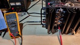
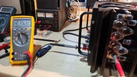
It's like this now, I can also set the left channel. I could only regulate the voltage across the 0.22 ohms down to 12.3mV. I wanted to move towards 11mV in the middle, but unfortunately that didn't work!
The temperature will also get warm now, like the right channel. The voltage measured as you say, I can adjust both channels from 0mV to approx. 6mV but not 27.5mV!!
Thank you for your effort!
The temperature will also get warm now, like the right channel. The voltage measured as you say, I can adjust both channels from 0mV to approx. 6mV but not 27.5mV!!
Thank you for your effort!
Attachments
Could you please indicate in the circuit diagram where you are measuring, but whatever it is, it is not the current through the 0.1R resistor as I have indicated.
As mentioned before, without having this info I can't give you any support.
Hans
As mentioned before, without having this info I can't give you any support.
Hans
- Home
- Amplifiers
- Solid State
- I have a Mark Levinson ML23 amplifier and I have the following problem! I can't set the quiescent current on the left channel with the! Poti is ok!