Hallo,
I am new to this forum and quite new to the audiophile world.
I need your expert advice to reverse-engineer a project that I would like to build with my CNC.
I have seen a thread regarding the Boenicke W5 clone. Very cool but I want to work on an existing alternative design.
In this Italian forum I have found a project called Rona created by a well-known speaker designer (A. Bellino – btw check some of its projects if you have time) who unfortunately stopped the activity. I tried to get in touch but no luck. I know for a fact that those speakers were built and sold on request in 2016/17.
Here
The design concept is very similar to the w5.
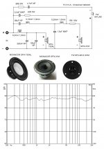
As you can see, there are drawings, drivers, crossover schematic and the frequency response.
In principle, all I need.
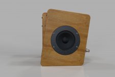
Using the benefit of the CNC, my idea is to tilt 8degrees the front and the back (keeping the overall internal volume), round some internal corners and maybe even integrate the reflex changing the section from round to square (with the same section area).
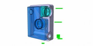
I have created the 3D model with the purpose to run some simulations.
I am pretty good at modelling, but a completelooser beginner at designing speakers. So, as expected, I got lost pretty quickly.
Here are my problems:
Woofer –SPH-130AL
· After removing the volume of the reflex, the tweeter and the woofer itself, the true volume of free air left in the box is about 3.35liter. If I force Winisd to work with that volume (and with the given spec of the reflex) the resulting Fs is 68Hz. Is that an issue? Can the woofer work properly with that volume of air?
Full-range SPX-31M
· The full-range driver can barely fit in that space. I know It is a "Closed-box" design, but it looks very "Closed" to me (0.17liter of free air). Once again Winisd would prefer different numbers…. Can that work?
Overall
· The drivers are firing in 3 different directions. What about the phase? Do I need to care?
· Is the diffraction an issue for this design? Rounded corners or not?
· Is the crossover working? Meaning: does it make sense to you guys? I simulate the Crossover in Vituixcad but with the values in the post nothing works for me. The response is all over the place. What do I do wrong?
· The project is from 2016 so maybe in 2022 I could use better drivers. Even the ones used on the Boenicke W5. Any advice?
I have 0 experience and 0 professional equipment to simulate and measure……..
I need some help to get to the finish line. I just don’t want to blindly copy a project with the risk that it doesn’t work. I would like to understand.
I bet that there are many experts in this forum who could run correct simulations to validate the design (or not).
I am more than happy to take care of the modelling, share the 3D and create dfx/toolpath for the CNC once I have confidence that the design could work.
Is someone interested?
Can someone help?
In my opinion this W5 alternative could be a very cool and cheap DIY project. Cool enough to compete with the w5 clone.
Thanks a lot
I am new to this forum and quite new to the audiophile world.
I need your expert advice to reverse-engineer a project that I would like to build with my CNC.
I have seen a thread regarding the Boenicke W5 clone. Very cool but I want to work on an existing alternative design.
In this Italian forum I have found a project called Rona created by a well-known speaker designer (A. Bellino – btw check some of its projects if you have time) who unfortunately stopped the activity. I tried to get in touch but no luck. I know for a fact that those speakers were built and sold on request in 2016/17.
Here
The design concept is very similar to the w5.
As you can see, there are drawings, drivers, crossover schematic and the frequency response.
In principle, all I need.
Using the benefit of the CNC, my idea is to tilt 8degrees the front and the back (keeping the overall internal volume), round some internal corners and maybe even integrate the reflex changing the section from round to square (with the same section area).
I have created the 3D model with the purpose to run some simulations.
I am pretty good at modelling, but a complete
Here are my problems:
Woofer –SPH-130AL
· After removing the volume of the reflex, the tweeter and the woofer itself, the true volume of free air left in the box is about 3.35liter. If I force Winisd to work with that volume (and with the given spec of the reflex) the resulting Fs is 68Hz. Is that an issue? Can the woofer work properly with that volume of air?
Full-range SPX-31M
· The full-range driver can barely fit in that space. I know It is a "Closed-box" design, but it looks very "Closed" to me (0.17liter of free air). Once again Winisd would prefer different numbers…. Can that work?
Overall
· The drivers are firing in 3 different directions. What about the phase? Do I need to care?
· Is the diffraction an issue for this design? Rounded corners or not?
· Is the crossover working? Meaning: does it make sense to you guys? I simulate the Crossover in Vituixcad but with the values in the post nothing works for me. The response is all over the place. What do I do wrong?
· The project is from 2016 so maybe in 2022 I could use better drivers. Even the ones used on the Boenicke W5. Any advice?
I have 0 experience and 0 professional equipment to simulate and measure……..
I need some help to get to the finish line. I just don’t want to blindly copy a project with the risk that it doesn’t work. I would like to understand.
I bet that there are many experts in this forum who could run correct simulations to validate the design (or not).
I am more than happy to take care of the modelling, share the 3D and create dfx/toolpath for the CNC once I have confidence that the design could work.
Is someone interested?
Can someone help?
In my opinion this W5 alternative could be a very cool and cheap DIY project. Cool enough to compete with the w5 clone.
Thanks a lot
Attachments
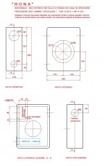
The link works for me. Anyway It just the link to the original post. The info are in the picture attached.
All based on published specs!
SPH-130AL - depends on your definition of 'properly', i.e. a T/S max flat alignment is ~5.029 L/60.2 Hz Fb, so based on this, no. That said, 3.35 L is fine if tuned to <~60.2 Hz, which it is at 68 Hz, so it's fine, just means that it will roll off sooner with less (mid) bass than the max flat alignment as your sim should show.
SPX-31M - its sealed alignment calculates a ~0.62 Qtc, so a good compromise between 0.5 (transient perfect and 0.707 (max flat).
The rest will have to wait or others to comment.
Thanks a lot!All based on published specs!
SPH-130AL - depends on your definition of 'properly', i.e. a T/S max flat alignment is ~5.029 L/60.2 Hz Fb, so based on this, no. That said, 3.35 L is fine if tuned to <~60.2 Hz, which it is at 68 Hz, so it's fine, just means that it will roll off sooner with less (mid) bass than the max flat alignment as your sim should show.
SPX-31M - its sealed alignment calculates a ~0.62 Qtc, so a good compromise between 0.5 (transient perfect and 0.707 (max flat).
The rest will have to wait or others to comment.
So the drivers and the box seems to work.
Next steps it is the validation of the crossover. As said my simulation makes no sense......
Awaiting for help...
Here is what I have done....
- I have created the drivers in vituixcad and I have simulated the FRD and ZMA using the Enclosure tool. I have inserted the volumes coming from the 3D models that I have created to have a realistic simulation.
- I have saved the FRD and ZMA of the drivers.
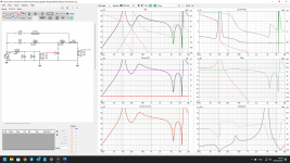
- I have simulated the crossover (only the woofer and the full range) following the scheme and the values of the 1st post, but maybe I am doing something wrong....
Attachments
You need to post .zma and .frd too. .vxp files do not contain frequency response and impedance data on their own.
Here are the .zma and .frd of the driversYou need to post .zma and .frd too. .vxp files do not contain frequency response and impedance data on their own.
Attachments
Your files are the responses generated by the enclosure tool and are not useful to generate a valid x-over.
See the VCad help page and the related pdf/video on how to create the impedance and response files to input in VCad.
See the VCad help page and the related pdf/video on how to create the impedance and response files to input in VCad.
Thanks.
I have seen the videos about tracing the zma and frd from the pictures of the. measurements (or manually inserting the values}.
This is what I have done to create the drivers in the first place..
Then I used the "just created" drivers and put them in the enclosure tool for the simulation. I wanted to see how they would behave in that specific enclosure.
Then I saved the responses again as I thought that the crossover would work better with the real behaviour.
For the crossover, should I just use the standard responses of the drivers from the manufacturer?
Last edited:
The new Boenicke use Accoya, a stabilised wood (think resin infused), might be worth checking out, as wood. movement will be your enemy.
Trace the curves of the manufacturer.Thanks.
I have seen the videos about tracing the zma and frd from the pictures of the. measurements (or manually inserting the values}.
This is what I have done to create the drivers in the first place..
Then I used the "just created" drivers and put them in the enclosure tool for the simulation. I wanted to see how they would behave in that specific enclosure.
Then I saved the responses again as I thought that the crossover would work better with the real behaviour.
For the crossover, should I just use the standard responses of the drivers from the manufacturer?
Design your baffle in the diffraction tool and export the responses for both speakers. If you want generate a full space set of responses, load the traced curve and check the option Directivity.
Calculate the volume in the enclosure tool and save the curves (2Pi).
Open the merger tool and load the low FR, the diffraction response and the traced curves. Adjust the level of the low part (if needed): the merging frequency is about 400-500Hz. Save them and load the FR and the ZR (created with the enclosure) in the main program. In the main program, when the driver is selected in the crossover tab, you have to input the exact x,y,z of the drivers on the baffle.
Most definitely!Overall
· The drivers are firing in 3 different directions. What about the phase? Do I need to care?
· Is the diffraction an issue for this design? Rounded corners or not?
· Is the crossover working?
Yes, it makes a difference if rounded enough for the BW, but being only done in the vertical plane not so much due to our hearing is horizontally acute, so IME just cosmetic in this case.
No clue about the XO, but thankfully those who are have taken over, so good luck with it as it looks like a well worth project.
Just an update,
I am still struggling with the mysteries of the crossover and until now I was not able to understand if the scheme in the first post is actually working.
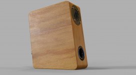
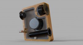
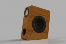
Meanwhile I started working on the box.
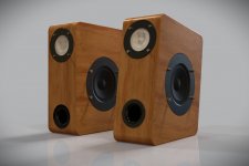
It is now very similar to the w5. Just slightly bigger. I kept the volumes of the "straight" version. I made some additional modification that should help.
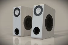
The idea would be to build a prototype in MDF (probably 4 slices) and glue them together.
Then move to the wood version.
The enclosure for me is ready. Have a look and let me know if you see some improvement.
The crossover is not.
If someone is interested, I can share my files.
Please give me a hand.
I am still struggling with the mysteries of the crossover and until now I was not able to understand if the scheme in the first post is actually working.
Meanwhile I started working on the box.
It is now very similar to the w5. Just slightly bigger. I kept the volumes of the "straight" version. I made some additional modification that should help.
The idea would be to build a prototype in MDF (probably 4 slices) and glue them together.
Then move to the wood version.
The enclosure for me is ready. Have a look and let me know if you see some improvement.
The crossover is not.
If someone is interested, I can share my files.
Please give me a hand.
Attachments
The scheme of the x-over in the first post is valid unless you do not change the drivers, the size of the front baffle and the position of the drivers on the baffle. Moreover, the speaker you modelled is slanted while the one of the 1st post is not and that makes a big difference. Basically, you need a new x-over.
That's too bad....
I like the slanted front.
So if I go for the simple box, I need just to copy the design. I could even avoid the cnc. It's a squared box.
If I want my cool design I need a new crossover and probably measurements knowing that I don't have the skills and the equipment to carry out.
Just for 8 deg tilt..... 😔😔
8 bloody deg
Thanks a lot anyway. At least you clarified what needs to be done.
I am not sure that the 8-degree slope of your design would massively impact on the qualities of this design.
If I could build the box easily, I would give it a try and adjust the Xover by ear. With the bass peaking at 100hz or so and the actual Xover to the mid rolling it in at 200-300Hz this shouldn't be problematic. and adjust tweeter level to sound balanced at your listening position.
The Xover may need more investigation to bring in the baffle step and diffraction aspects for the mid. Tweeter just level adjustment I imagine, and maybe bass not so peaked. But maybe that is what you intended?
Thanks, I was also thinking the same.I am not sure that the 8-degree slope of your design would massively impact on the qualities of this design.
If I could build the box easily, I would give it a try and adjust the Xover by ear. With the bass peaking at 100hz or so and the actual Xover to the mid rolling it in at 200-300Hz this shouldn't be problematic. and adjust tweeter level to sound balanced at your listening position.
The Xover may need more investigation to bring in the baffle step and diffraction aspects for the mid. Tweeter just level adjustment I imagine, and maybe bass not so peaked. But maybe that is what you intended?
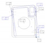
It was not clear from the rendering, but the change is minimal. I was careful to maintain the relative distance of the drivers and the volume of the enclosure.
In the picture, I have overlapped the 2 models (original and modified) matching the position of the subwoofer. As you can see the full range is basically in the same place. The twitter is a bit lower but it is a matter of 3cm. I really had to move up the reflex port, otherwise it would clash on the bottom.
Moreover the drivers are emitting on 3 completely different planes so the tilt should not impact the phase like it would do in a traditional 3 ways (or at least the impact should be as the original).
So I think I will give it a go. I want to create some bookshelf speakers for my desk and maybe pair them with a little subwoofer. The project is not meant to be a 5K€ system.
I have created the 3d of all. Now I will create the toolpath and see how it goes.
They might turn out really nice and sound good as well............
Unfortunately, I am not able to crate a Xover.
Attachments

It's the SH-130AL crossover that's causing the huge peak at about 100 Hz. Try adding a 10-20 ohm resistor in series with the 100 uF cap. Adjust the resistor value so the SH-130AL response blends with the SPX-31M response. I modeled just the SH-130AL in VituixCad and my results match yours.
PS: The inside diameter of the port tube is 35 mm.
PS: The inside diameter of the port tube is 35 mm.
- Home
- Loudspeakers
- Multi-Way
- Boenicke W5 Alternative