Hi again!
Going through some of the old school amplifiers I have accumulated over the years, and I still have a Hifonics Boltar VIII, A few years back I posted on this forum looking for the connectors. I did contact Steve at Zed who would sell me a used set for $100, not worth that to me so I will probably remove the connectors and replace them with something else or solder wires directly to the board.
While exchanging emails with Steve, I started to discuss the updates/upgrades for this amplifier. It is a service he offers for a reasonable charge, but it is more that I want to spend on it. Unfortunately, he has no support for DIY types. It would have been great if he sold a parts kit and instructions.
So, first question is- Anyone else know the details of the upgrade process? Replacing the capacitors is pretty obvious, but he also mentions modifying the power supply (drive circuit, and regulation). He also mentioned those upgrades in this post: https://www.diyaudio.com/community/threads/hifonics-boltar-viii.367163/
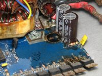
Second question is- even though I think this amplifier works, there are two resistors that look to be "crunchy". One is labeled R14, the other (right next to it) I can't read. My thought is to remove them, and measure but that may not be accurate considering their appearance. Anyone know what this is supposed to be?
Also would love some schematics, if they are out there.
Thanks!
Going through some of the old school amplifiers I have accumulated over the years, and I still have a Hifonics Boltar VIII, A few years back I posted on this forum looking for the connectors. I did contact Steve at Zed who would sell me a used set for $100, not worth that to me so I will probably remove the connectors and replace them with something else or solder wires directly to the board.
While exchanging emails with Steve, I started to discuss the updates/upgrades for this amplifier. It is a service he offers for a reasonable charge, but it is more that I want to spend on it. Unfortunately, he has no support for DIY types. It would have been great if he sold a parts kit and instructions.
So, first question is- Anyone else know the details of the upgrade process? Replacing the capacitors is pretty obvious, but he also mentions modifying the power supply (drive circuit, and regulation). He also mentioned those upgrades in this post: https://www.diyaudio.com/community/threads/hifonics-boltar-viii.367163/
Second question is- even though I think this amplifier works, there are two resistors that look to be "crunchy". One is labeled R14, the other (right next to it) I can't read. My thought is to remove them, and measure but that may not be accurate considering their appearance. Anyone know what this is supposed to be?
Also would love some schematics, if they are out there.
Thanks!


Desolder the resistors. The value may be printed under them.
Yup! Thank you! Any ideas on the rest of the "upgrades"??
Not really. The amp worked well for years. Return it to what it was when new and use it.
For these resistors, use flameproof (ceramic coated) and mount them up about 1/4" above the board to reduce the heat being transferred to the board and pads.
As far as the caps go, you need to replace any that are leaking or out of tolerance. The ones in the primary were the ones that caused the most problems. Use 105C caps if they'll fit.
Not really. The amp worked well for years. Return it to what it was when new and use it.
For these resistors, use flameproof (ceramic coated) and mount them up about 1/4" above the board to reduce the heat being transferred to the board and pads.
As far as the caps go, you need to replace any that are leaking or out of tolerance. The ones in the primary were the ones that caused the most problems. Use 105C caps if they'll fit.
Considering the technology for capacitors has improved, any advantage to using larger ones on the rail power? Give it more headroom? I have not pulled the board off the heat sink yet, but I am guessing that the group of 2700uF 25V capacitors near the power input are across the 12V supply, then there are some 2200uF 50V caps that are probably across the rail power.
Any shot at finding a schematic for this?
Higher value caps will do nothing. This isn't like the 60Hz sine wave that you have for home/commercial amps. The secondary power supply caps are charged by a square wave about 50k times a second. You could probably go with 1/10 the original value and hear no difference in the amp.
In an amp that's hard on primary filter caps, you can go up in voltage rating and get a lower ESR, all else being equal but low ESR caps of the same voltage will be perfectly fine.
Cap tech hasn't changed much in wet electrolytic caps. There have been advantages in other types of caps used in computers and such but those types of caps aren't used in car amps.
If Mr. Mantz won't supply it, there is virtually no chance to get a diagram.
Any shot at finding a schematic for this?
Mantz said in a previous (old) thread that the schematics for those earlier amps only existed in his head.
Higher value caps will do nothing. This isn't like the 60Hz sine wave that you have for home/commercial amps. The secondary power supply caps are charged by a square wave about 50k times a second. You could probably go with 1/10 the original value and hear no difference in the amp.
In an amp that's hard on primary filter caps, you can go up in voltage rating and get a lower ESR, all else being equal but low ESR caps of the same voltage will be perfectly fine.
Cap tech hasn't changed much in wet electrolytic caps. There have been advantages in other types of caps used in computers and such but those types of caps aren't used in car amps.
If Mr. Mantz won't supply it, there is virtually no chance to get a diagram.
Thanks again for your advice on this! I thought larger capacitors on the rail would help with power spikes that may push the power supply to it's limits. Like, those "stiffening caps" many put on their amplifiers. But, I agree- if it worked OK before no reason to mess with it.
Going to start ordering parts soon. Found some 1.3K 3W flame proof resistors (the old ones tested good). Tracking down the capacitors now. When I do old CRT's, I just replace all of them- but it sounds like you think that may not be needed? The only caps I see on the primary side are the four 2700uF/25V ones across the 12V input. If you think I am good with just replacing those four, less work for me!
I did notice another cap on one of those daughter boards that has some silver showing on the side. No other reason to think it is bad, but maybe I should replace that one too? While inspecting, I also saw another cracked resistor on the daughter board. based on the other board that looks identical, I guess it is a 7.5K Ohm 1% resistor.
There are 3 daughter cards, 2 look identical. All have small electrolytic on them. Safe to leave them all alone?
Thanks again.
The covering on the capacitors is a shrink-wrap. Sometimes it shrinks a bit more than expected. I've seen and tested many caps like that and they were OK.
If you want to pull and check a couple of the ones of that make, you can do it but I'd expect them to be OK.
A quick check for leaking electrolyte is to heat the terminals enough to melt the solder. If the cap has leaked electrolyte (the main reason for the cap to fail) you will smell the electrolyte.
Sounds like the only ones I should replace as "preventative" are the four across the 12V supply?
You can test those by heating, by removing them to see if they're leaking or by checking them with a capacitance meter.
I don't see any obvious leakage. The photo below shows leaky caps. The areas where the board looks wet and the black substance on the bottom of the cap are electrolyte.
I don't see any obvious leakage. The photo below shows leaky caps. The areas where the board looks wet and the black substance on the bottom of the cap are electrolyte.
Attachments
Ha! With the power wires soldered directly to the PWB. Guess those connectors being lost is very common. 🙂
I may replace them anyway. Probably put 4700uF in there if the fit.
I may replace them anyway. Probably put 4700uF in there if the fit.
The wires are OEM. The photos are from a series 7 amp.
Don't try to second-guess the manufacturer unless there is a known reliability issue. The original caps held up perfectly fine. They may not even need to be replaced.
Don't try to second-guess the manufacturer unless there is a known reliability issue. The original caps held up perfectly fine. They may not even need to be replaced.
You need to clean up all of that corrosion with acetone (and maybe 400g sandpaper) and check the condition of the area around the vias/feedthroughs/pads. If the electrolyte has penetrated into the board, the fiberglass will need to be cut away until you get back to clean fiberglass. Some reconstruction or modification of the board may be necessary.
More isn't necessarily better.
More isn't necessarily better.
When the electrolyte penetrates the board, the board becomes conductive and can burn when voltage is applied. This can happen at any time, even when the amp isn't being used.
Do you have a bright flashlight?
Do you have a bright flashlight?
Do you have a bright flashlight?
Bright is relative. LOL! I have a LED work light.
- Home
- General Interest
- Car Audio
- Blowing the dust off my Hifonics Boltar VIII