Spec'ing #'s for upcoming tube amp project for buddy w/ plus size mancave...
Have decided on below EICO super mod schema which uses quad of 7591's... however I'll be using 6GM5's. B+ lists 450vdc @ 320ma using full wave SS w/ CT PT.
Three Q's related:
1. Should PT B+ supply be center tapped (2 diodes) or not using bridge?
2. Related to first Q, what should AC V spec be (CT or not) to achieve full load DC requirement?
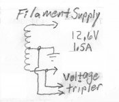
3. See below hand scribble- can I hook fixed bias voltage tripler (-19v) up to 1/2 preamp fil supply?
Thanks,
Jim
Have decided on below EICO super mod schema which uses quad of 7591's... however I'll be using 6GM5's. B+ lists 450vdc @ 320ma using full wave SS w/ CT PT.
Three Q's related:
1. Should PT B+ supply be center tapped (2 diodes) or not using bridge?
2. Related to first Q, what should AC V spec be (CT or not) to achieve full load DC requirement?
3. See below hand scribble- can I hook fixed bias voltage tripler (-19v) up to 1/2 preamp fil supply?
Thanks,
Jim
Attachments

For FWCT (two diodes), you need 320-0-320 VAC at rated load.
But you also need a tap on the same secondary for fixed bias operation.
For FWB (four diodes), you need 0-320 VAC at rated load.
But you have to get the bias supply voltage from somewhere else, or use self-bias.
Tripler off the filament winding should work, if filtered well.
If your AC line runs high, consider two series diodes each in the FWCT for extra blocking.
Last edited:
Planning on fixed bias, so you're saying (-)grid tripler needs AC supply to come from B+ tap instead of fil tap, even if fil tap CT is grounded?
No, that;s just the traditional place. A tripler off half the grounded filament winding should work, if done carefully.
If your AC line runs high, consider two series diodes each in the FWCT for extra blocking.
Does using four diodes FWB instead of two FWCT inject any more switching noise into the DC? Sure it can be mitigated w/ higher speed/better rectifiers... but at the design stage... cost is the same for perhaps better dynamics? Or is 4v2 really a moot point after LC filtering?
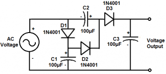
Pictures speak volumes...
If you use a centre tap, you can get your bias voltage from a tap. If you're using a tube rectifier, you'll beed this kind...

If you are using SS, the using 4 diodes for a bridge vs 2 diodes and the centre tap is funcionally the same, but you need to get the bias voltage from a separate place like the tripler @rayma suggested.
For B+:

For C-: Ground the + and connect the heaters across Vp. for 6V3 input, you'll get ~ 25V for bias (6.3×1.414)3=26.72

If you use a centre tap, you can get your bias voltage from a tap. If you're using a tube rectifier, you'll beed this kind...
If you are using SS, the using 4 diodes for a bridge vs 2 diodes and the centre tap is funcionally the same, but you need to get the bias voltage from a separate place like the tripler @rayma suggested.
For B+:
For C-: Ground the + and connect the heaters across Vp. for 6V3 input, you'll get ~ 25V for bias (6.3×1.414)3=26.72
Noise shouldn't be a problem, but you can look into a HV snubber across the secondary to reduce switching noise.Does using four diodes FWB instead of two FWCT inject any more switching noise into the DC? Sure it can be mitigated w/ higher speed/better rectifiers... but at the design stage... cost is the same for perhaps better dynamics? Or is 4v2 really a moot point after LC filtering?
That's an odd choice of amplifiers to build, IMO. Do you have the original Eico output transformers on hand?
GG-
Don't have, that's why I was asking- spec'ing out new PT for this build. If you have better 7591/7868/6GM5 quad example, please share
KBX-
Thx for input...
Know I can use B+ winding tap for such purpose, but was hoping to use E tripler off half 12.6V grounded heater tap cuz I'm familiar with lower voltage app for grid bias. Currently using tripler schema below off unused 5V tap which provides -19V.
Being that half wave rectifier can be used if smoothed- I get that based on your & EICO mods examples. But I'd like to use what I asked if possible-
Maybe I'm stubborn; IDK- lol
Jim
Attachments
GG-
Don't have, that's why I was asking- spec'ing out new PT for this build. If you have better 7591/7868/6GM5 quad example, please share
KBX-
Thx for input...
Know I can use B+ winding tap for such purpose, but was hoping to use E tripler off half 12.6V grounded heater tap cuz I'm familiar with lower voltage app for grid bias. Currently using tripler schema below off unused 5V tap which provides -19V.
Being that half wave rectifier can be used if smoothed- I get that based on your & EICO mods examples. But I'd like to use what I asked if possible-
Maybe I'm stubborn; IDK- lol
Jim
Fair enough. I assume you have the 6GM5s on hand, otherwise a PP 6550 would be much easier to build. ;-) You'll need to find a suitable output transformer, from the data sheet it looks like 3300 ohm p-p, capable of 150 mA per winding, minimum 60 watts output, preferably 100 watts. A Hammond 1650KA would be a good candidate. Of course, that exact circuit is not going to work with a different output transformer. You'll have to recalculate the feedback and whatever low-pass elements are encorporated in the original design to avoid high-frequency instability.
- Home
- Amplifiers
- Tubes / Valves
- PT questions