Well...I have proof!
First hand:
2CV puts out 29HP but it feels like 30!
Second hand:
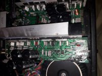
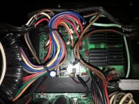
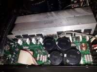
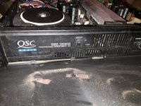
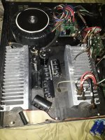
Yesterday I got for free a broken QSC RMX1850 HD, one of the earliest QSC to introduce a switching class B for the upper part of a class H amplifier.
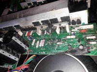
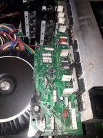
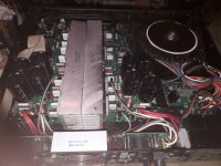
Apart from being a very heavy unit employing 4 rectifier bridges the only thing that was completely fried was the protection circuitry on one channel..I mean everything starting with R4...and not a single power transistor, not one!
I'm thinking to remove all the protections , scrap the class B upper part of the amplifier , remove 8 power transistors, rewiring everything for half rail replace the heatsinks with the vertical flow ones, screw some holes into the case for air convection and I'll have the most reliable 120 watts/8ohm amplifier with that 10 kg transformer...thinking of faster transistors, rectifiers and op-amps too , 0.44 ohms instead of 0.22 ohms emitter resistors as in the older versions and maybe the kenwood l-01a driver stage rewiring 😉
First hand:
Second hand:
Yesterday I got for free a broken QSC RMX1850 HD, one of the earliest QSC to introduce a switching class B for the upper part of a class H amplifier.
Apart from being a very heavy unit employing 4 rectifier bridges the only thing that was completely fried was the protection circuitry on one channel..I mean everything starting with R4...and not a single power transistor, not one!
I'm thinking to remove all the protections , scrap the class B upper part of the amplifier , remove 8 power transistors, rewiring everything for half rail replace the heatsinks with the vertical flow ones, screw some holes into the case for air convection and I'll have the most reliable 120 watts/8ohm amplifier with that 10 kg transformer...thinking of faster transistors, rectifiers and op-amps too , 0.44 ohms instead of 0.22 ohms emitter resistors as in the older versions and maybe the kenwood l-01a driver stage rewiring 😉
Attachments
-
 Screenshot_20220616-123210_Word.jpg169.9 KB · Views: 560
 -
 Screenshot_20220616-123230_Word.jpg192.3 KB · Views: 611
 -
 20220616_122853.jpg616.2 KB · Views: 690
 -
 20220616_122839.jpg632.8 KB · Views: 438
 -
 20220616_122911.jpg559.8 KB · Views: 411
 -
 20220616_122935.jpg531.1 KB · Views: 401
 -
 20220615_201536.jpg457.5 KB · Views: 395
 -
 20220615_201547.jpg532.2 KB · Views: 481
 -
 20220615_201622.jpg510 KB · Views: 384
 -
 20220615_201556.jpg545.9 KB · Views: 379
 -
 20220615_201724.jpg551.9 KB · Views: 571
Last edited:
NOW you see why you never do without DC protection, and why you should NEVER use a @#$&*% triac crowbar on the output of a solid state amplifier for the purpose! Time to buy a new PCB - translation in practical terms: new amplifier. $400 for a PCB module and $200 service fee and you still have an old amp full of dust and cigarette smoke. Which is why you got it free.
The 2450 was the first of its kind, not the 1850. It’s the same amp with the quad rails reduced from 55V to 44V, and the same transformer VA capacity. In practical terms it produces the same REAL power and the same loudness from the speakers bridged into 4 ohms as its predecessor does, and does so with less heat. A little more clean headroom on the 2450, but when blasted to distortion the 1850 “sounds better” when running low impedance loads. The power supply voltage/current tradeoff is simply a better match for that. Back before this class of amplifier was replaced by class D, this was THE most copied design on the planet. They all made the same thing, with just varying levels of quality.
It is a very good “donor amp” to rebuild in various forms. Original circuitry, original with upgrades, something new and custom. And certainly possible to run from just the low rail at high reliability. You could rebuild the 4-diode-bridge power supply to run two secondaries per channel in parallel instead of series. The coil voltages are the same, but I’d still use a separate diode bridge for each. I would not “do away with protections” entirely, though. Do not use a crowbar. Either a large ice cube relay (you need a big one, you see what the monster transformer did to the board running into a short) or mosfet-based one.
well...in my country nothing is really for free...NOW you see why you never do without DC protection, and why you should NEVER use a @#$&*% triac crowbar on the output of a solid state amplifier for the purpose! Time to buy a new PCB - translation in practical terms: new amplifier. $400 for a PCB module and $200 service fee and you still have an old amp full of dust and cigarette smoke. Which is why you got it free.
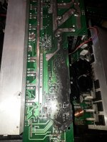
Anyway...this amp worked for 12...15 years in the biggest disco around here regularly at clipping volumes...I'd say it did its job for a made in china product.You need to see how bad the heatsink is.Besides the filtering caps are simply dry...weighing almost thhe weight of their aluminium cans...
And it is naturally DC protected as the output is capacitor coupled as in all qsc products. Good speakers are way more expensive than amplifiers . I fixed one qsc USA 1310 amp in the past ...that had about 4 tranz bvurned...just replaced them...It worked for another few yeras patched like that.
And what's wrong with the crowbar? That's the only professional way to protect your power electronics and it works...It obviously worked here even if it died.By the way, the triac isn't dead, just the pcb 🙂
Last edited:
Besides I have a question to reiterate...I was told in the past that the Sziklai pair is stable if the input trz has a significantly higher FT than the output trz...well...this amp worked about 12 years close to it max capacity while having both the driver and the output trz FT= 30mhz.The driver's FT is prone to get even lower when driving 4 pallelled pairs around 5...10 amps each...
This line of amps disprove the higher FT theory in my view.Where's the theoretical compensation?
This line of amps disprove the higher FT theory in my view.Where's the theoretical compensation?

This version is not “naturally DC protected”. The center tap of the power supply IS connected to the center connection of the rail caps. Unlike earlier designs where the center between the rail caps actually floats. This change was necessary in order to accommodate the class H stepped voltage supply. You can get DC to the speaker here - which is probably what happened. If the rail caps are dried out that may be why. I bet they didn’t go down evenly - resulting in uneven clipping which puts out an average DC, which then shorted the crowbar and it just stayed that way till the board toasted. PCB mount caps never hold up under long term high ripple useage the way computer grade soup can caps used to. After 12 to 15 years of disco duty it doesn’t surprise me at all - I’ve re-capped plenty of those old QSCs. The crowbar did protect the loudspeaker - but for the club owner was still out $600 for a new amp. Probably a class D that will fail in a year or two instead of 12.
The fT of the output transistors falls at high current too. The driver fT never falls below the composite output fT. The CFP of a 1503x and one C5200 per 8 ohm load is proven to be pretty stable, for up to at least 6 output pairs. Manufacturers wouldn’t just copy this and use it if it didn’t have some proven field reliability. Some things “just work”.
The fT of the output transistors falls at high current too. The driver fT never falls below the composite output fT. The CFP of a 1503x and one C5200 per 8 ohm load is proven to be pretty stable, for up to at least 6 output pairs. Manufacturers wouldn’t just copy this and use it if it didn’t have some proven field reliability. Some things “just work”.
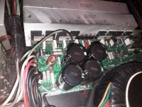
You may be right with all of the above for this model except the caps measure 16 000uf...all of them.I don't have an esr meter right now...They're not well known(Nover) unlike the old ones used in USA series which I remember being kinda low ESR type.I already prepared the new heatsinks and I'll go with the old fashioned cap copuled outputs of the old models.Now...I don't really like the power transformer as it is too unnecessay big and heavy for this downscaling i'm planning but at least I know this one will never die in my arms...If the rail caps are dried out that may be why. I bet they didn’t go down evenly - resulting in uneven clipping which puts out an average DC, which then shorted the crowbar and it just stayed that way till the board toasted.
Attachments
Was it he who originated the inside-out power amp, where the traditional output from the output transistor emitters was connected to ground and the actual audio was taken from the ungrounded center-tap of the power supply? So that if your band blew up the amp the output wouldn't go to a rail and set your speakers on fire?
This appeared in some later Peavey combo bass amps, too....
This appeared in some later Peavey combo bass amps, too....
Usually in qsc amps the outputs are the collectors that form a virtual ground and the midtap of the filtering capacitors are used to connect the other end of the speaker. It seems he's done it first for Pignose, but it clearly became his own QSC brand marck that has at least the virtual ground output in every amp except some plx and cx apparently...I haven't checked all qsc modern iterrations...they are too many.I'm told that for the scrap rmx model i got they used the midtap of the transformer artached to the midtap of the filtering caps which they didn't in their most USA iconic models where they used an op-amp to create the dc refference...I already disconected all the wires.Can't check it. No relays are found in his amps, at least not in the ones having this structure, not even in this rmx model...but this is already a 2000...2005 model where manufacturing was externalized to China.Was it he who originated the inside-out power amp, where the traditional output from the output transistor emitters was connected to ground and the actual audio was taken from the ungrounded center-tap of the power supply? So that if your band blew up the amp the output wouldn't go to a rail and set your speakers on fire?
This appeared in some later Peavey combo bass amps, too....
https://www.diyaudio.com/community/threads/qsc-audio-floating-supply-amplifiers.167716/post-2204200
Last edited:
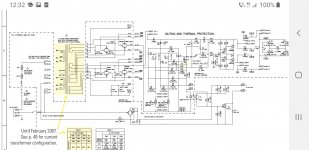
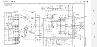
If you look carefully at the schematic for the 1850, there are two connections labeled “CT A” and “CT B”, where the trafo windings connect together. The amp shows “CT A” connecting to the speaker output node between the supply caps.
The class H rail switching will not work properly if that center isn’t nailed down. The mid rail voltage, relative to the upper rail voltage will wander around depending on loading, rather than staying at about half. The class H versions aren’t as fault tolerant as the old classic models because of this, but the heat produced in regular class AB at these power levels is unworkable. The RMX is still a pretty solid design - their install versions are almost identical circuit wise - just some re-packaging and adding features like 70/100 volt output trafos.
If you take their old models and upgrade to MJ15024/5 outputs and MJE15032/3 drivers and put in new supply caps you can beat the living daylights out of them with impunity.
I fixed a mj15024 usa 1310 model once ...not sure how bad the original transistors are though...yet his heatsink without a fan won't work a full minute at full power...QSC was very minimalistic and probably the real pioneer of fan cooling every gram of aluminium...That's gonna change in my downscaled 2x 120 watts rmx for which i prepared passive cooling.
Coul you share some repair wisdom upon your best pick for replacing the original capacitors in a model without transformer's center tap connection, the old USA connection model?If you look carefully at the schematic for the 1850, there are two connections labeled “CT A” and “CT B”, where the trafo windings connect together. The amp shows “CT A” connecting to the speaker output node between the supply caps.
Modern Panasonic or Nichicon, 3000 or more hours at 105C. Buy 15000 hour caps if you want to spend the $. They never used anything that good originally, and new ones will fit the old PCBs from last century. And I’ve seen some real crap used for replacements, which only went out again.
USA1310 is the only one which ever used 15022’s originally. At +/-93 volts it’s the only thing you CAN use. A bit less supply voltage than the PL700, and six more output transistors - which ought to tell PL owners something. Their biggest problem of course was heat. It is too much for class AB Unless it’s the size of a Krell or old Bose 1801. It’s the straw that broke the Camel’s back. I have two of them still, but not in service anymore. First thing to go out? The caps of course. Never burnt out a transistor - and I was using them to drive Lab Horns (translation: hard service). According to schematics early 1300’s and early MX series had D424/B554 outputs - which some argue are better than 15024’s. I used them to rebuild CS800’s back in the 80’s. But unobtainuim now. All of the smaller 200, 300 watt per channel ish units I’ve seen used cheaper output types. Those should go and be upgraded to 15024. It’s not like you can buy a cheaper transistor cheaper anymore unless it’s in a plastic case, and all the old ones take TO-3’s. When I get one of these it’s usually been worked on several times with a hodge-podge of mismatched output transistors in it (and bad caps).
USA1310 is the only one which ever used 15022’s originally. At +/-93 volts it’s the only thing you CAN use. A bit less supply voltage than the PL700, and six more output transistors - which ought to tell PL owners something. Their biggest problem of course was heat. It is too much for class AB Unless it’s the size of a Krell or old Bose 1801. It’s the straw that broke the Camel’s back. I have two of them still, but not in service anymore. First thing to go out? The caps of course. Never burnt out a transistor - and I was using them to drive Lab Horns (translation: hard service). According to schematics early 1300’s and early MX series had D424/B554 outputs - which some argue are better than 15024’s. I used them to rebuild CS800’s back in the 80’s. But unobtainuim now. All of the smaller 200, 300 watt per channel ish units I’ve seen used cheaper output types. Those should go and be upgraded to 15024. It’s not like you can buy a cheaper transistor cheaper anymore unless it’s in a plastic case, and all the old ones take TO-3’s. When I get one of these it’s usually been worked on several times with a hodge-podge of mismatched output transistors in it (and bad caps).
If memory serves me well I remember USA1310 having some tall metalic brown capacitors which are nothing like the black ones in the photos i find online, telling me they were some lower esr variety...anyway...i might just use some cheap JB caps 10kuF/80v as they weigh double than the original 18kuF/50v i got from rmx1850hd...8 of them costs me like 40 bucks at a local store.We still have those real stores where you pay like 50...100%more to get the parts, but you have them available right away...I had good experiences with these unknown JB parts and they clearly won't cost me a fortune.Probably they cost 20 bucks online...but transport cost too so I get even.
The output is kept quite firmly by the op amp's dc refference while the class B stage on top is refferenced between supply rails .I'd say using the mid transformer tap is allowing for lower quality leaky capacitors , not so sure it has anything to do with the crossover switching of the class b amp.The class H rail switching will not work properly if that center isn’t nailed down. The mid rail voltage, relative to the upper rail voltage will wander around depending on loading, rather than staying at about half.
But the relative voltage between upper and lower rails will move around. Even with perfect capacitors if the load on the lower rail is higher than the load on upper rail, the lower rail gets dragged down much faster if you are just relying in series capacitors to divide the voltage. Resulting the the VCE on the output transistor being much higher when the rails switch.
If this actually worked properly without the supply center tap no one would bother with the multiple coils. You would just use a stack of four capacitors fed by one transformer winding and tap the rail switches at the nodes between them. I’m sure it’s been tried, and failed with a string blown output transistors to show for it.
It works for a single set of rails because the average loading between the two is the SAME.
And even the best PC-board-mount capacitors that were available in 1980 couldn’t hold a candle to what is in the RMX amplifiers of today. Yeah, they are “cheaper“ caps but the widespread use of switch mode power supplies today had forced the development of better ones than what we used to have. Doesn’t anybody remember FP cans? Yuck…
- Home
- Amplifiers
- Solid State
- Most underrated audio designer by the audiophile community: Pat Quilter