I posted in Spice model page, try it.
https://www.diyaudio.com/community/threads/vacuum-tube-spice-models.243950/post-7046908
https://www.diyaudio.com/community/threads/vacuum-tube-spice-models.243950/post-7046908
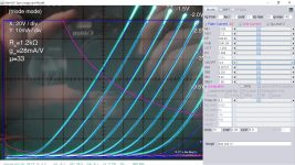
Looking at Koonw's graphs, he shows the triode strapped parameters, and the triode curve fit looks good. In your simulation you should be able to use the tetrode model and simply connect g2 to the plate.
Yes that is correct, but anyway I built the triode model as requested.
Code:
**** 6E6P-T ** Advanced Grid Current **********************************
* Created on 06/14/2022 04:15 using paint_kit.jar 3.1
* www.dmitrynizh.com/tubeparams_image.htm
* Plate Curves image file: 6e6p-e-t.png
* Data source link:
*----------------------------------------------------------------------------------
.SUBCKT 6E6P-T 1 2 3 ; Plate Grid Cathode
+ PARAMS: CCG=15P  CGP=0.05P CCP=5.9P
+ MU=33.95 KG1=37.3 KP=398.95 KVB=1941.84 VCT=-1.469 EX=1.098
+ VGOFF=-0.6 IGA=0.00107 IGB=0.201 IGC=9.92 IGEX=1.66
* Vp_MAX=200 Ip_MAX=140 Vg_step=0.5 Vg_start=0 Vg_count=11
* Rp=4000 Vg_ac=55 P_max=8.3 Vg_qui=-48 Vp_qui=300
* X_MIN=16 Y_MIN=64 X_SIZE=865 Y_SIZE=598 FSZ_X=1296 FSZ_Y=736 XYGrid=false
* showLoadLine=n showIp=y isDHT=n isPP=n isAsymPP=n showDissipLimit=y
* showIg1=y gridLevel2=y isInputSnapped=n
* XYProjections=n harmonicPlot=n dissipPlot=n
*----------------------------------------------------------------------------------
E1 7 0 VALUE={V(1,3)/KP*LOG(1+EXP(KP*(1/MU+(VCT+V(2,3))/SQRT(KVB+V(1,3)*V(1,3)))))}
RE1 7 0 1G  ; TO AVOID FLOATING NODES
G1 1 3 VALUE={(PWR(V(7),EX)+PWRS(V(7),EX))/KG1}
RCP 1 3 1G   ; TO AVOID FLOATING NODES
C1 2 3 {CCG} ; CATHODE-GRID
C2 2 1 {CGP} ; GRID=PLATE
C3 1 3 {CCP} ; CATHODE-PLATE
RE2 2 0 1G
EGC 8 0 VALUE={V(2,3)-VGOFF} ; POSITIVE GRID THRESHOLD
GG 2 3 VALUE={(IGA+IGB/(IGC+V(1,3)))*(MU/KG1)*(PWR(V(8),IGEX)+PWRS(V(8),IGEX))}
.ENDS
*$
Attachments
I just want to understand is it how it was supposed to be? In model anode current is practically doubled.

Thank you for pointing out. Here is the correct model:
Code:
*** 6E6P_E_T ** Advanced Grid Current *********************posted correction*************
* Created on 06/15/2022 09:28 using paint_kit.jar 3.1
* www.dmitrynizh.com/tubeparams_image.htm
* Plate Curves image file: 6e6p-e-t.png
* Data source link:
*----------------------------------------------------------------------------------
.SUBCKT 6E6PE-T 1 2 3 ; Plate Grid Cathode
+ PARAMS: CCG=15P  CGP=0.05P CCP=5.9P
+ MU=33.95 KG1=74.23 KP=398.95 KVB=1941.84 VCT=-1.469 EX=1.098
+ VGOFF=-0.6 IGA=0.00107 IGB=0.201 IGC=9.92 IGEX=1.66
* Vp_MAX=200 Ip_MAX=70 Vg_step=0.5 Vg_start=0 Vg_count=11
* Rp=4000 Vg_ac=55 P_max=8.3 Vg_qui=-48 Vp_qui=300
* X_MIN=16 Y_MIN=64 X_SIZE=865 Y_SIZE=598 FSZ_X=1296 FSZ_Y=736 XYGrid=false
* showLoadLine=n showIp=y isDHT=n isPP=n isAsymPP=n showDissipLimit=y
* showIg1=y gridLevel2=y isInputSnapped=n
* XYProjections=n harmonicPlot=n dissipPlot=n
*----------------------------------------------------------------------------------
E1 7 0 VALUE={V(1,3)/KP*LOG(1+EXP(KP*(1/MU+(VCT+V(2,3))/SQRT(KVB+V(1,3)*V(1,3)))))}
RE1 7 0 1G  ; TO AVOID FLOATING NODES
G1 1 3 VALUE={(PWR(V(7),EX)+PWRS(V(7),EX))/KG1}
RCP 1 3 1G   ; TO AVOID FLOATING NODES
C1 2 3 {CCG} ; CATHODE-GRID
C2 2 1 {CGP} ; GRID=PLATE
C3 1 3 {CCP} ; CATHODE-PLATE
RE2 2 0 1G
EGC 8 0 VALUE={V(2,3)-VGOFF} ; POSITIVE GRID THRESHOLD
GG 2 3 VALUE={(IGA+IGB/(IGC+V(1,3)))*(MU/KG1)*(PWR(V(8),IGEX)+PWRS(V(8),IGEX))}
.ENDS
*$
Attachments

- Home
- Amplifiers
- Tubes / Valves
- 6Э6П-E and 6Э6П-ДР spice models