Very similar topology to Eli’s El Cheapo, LTP driver/splitter in front of a PP output stage. The EC has a CSS under the LTP.
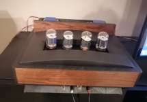
Our build was Class A, triode, puts out a mighty 3.2w and sounds absolutely fabtastic.
dave
Our build was Class A, triode, puts out a mighty 3.2w and sounds absolutely fabtastic.
dave
Just checked out a 6S7G data sheet, as that's a new one on me. Curves and tube constants look a lot like 12AT7/ECC81.
mu = 60
gm = 4mA/V
rp = 15k
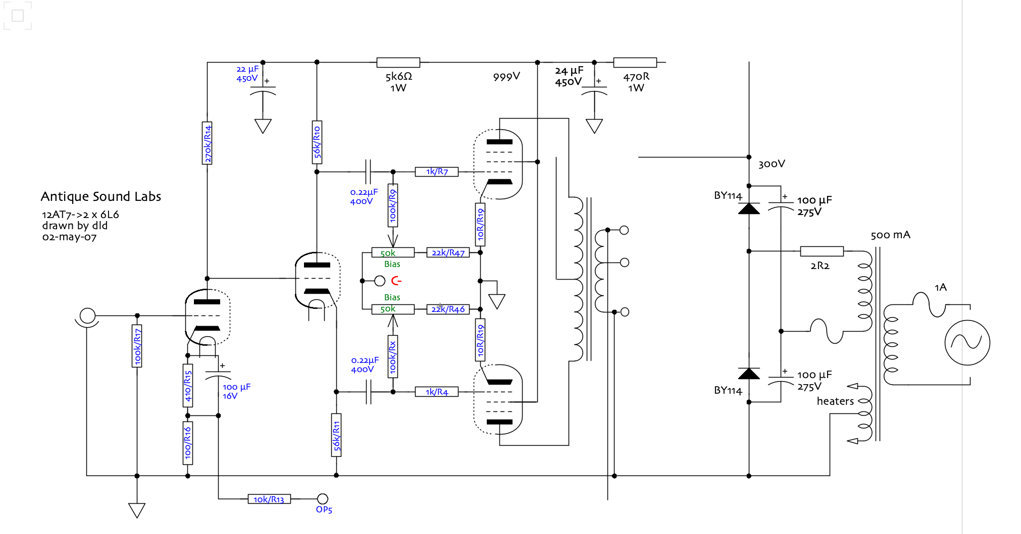
One big difference between Eli's El Cheapo and this design is that this one's phase splitter/driver is a paraphase inverter.
https://www.valvewizard.co.uk/paraphase.html
Eli's El Cheapo uses a 12AT7 as a long-tailed pair with a negative supply to the cathodes.
Using an 8k ohm primary on the OPT for pp 12AV5GA is a nice idea, imo. The higher-than-usual primary impedance will reduce the output power but increase the damping factor a bit, and reduce THD a little.
mu = 60
gm = 4mA/V
rp = 15k
One big difference between Eli's El Cheapo and this design is that this one's phase splitter/driver is a paraphase inverter.
https://www.valvewizard.co.uk/paraphase.html
Eli's El Cheapo uses a 12AT7 as a long-tailed pair with a negative supply to the cathodes.
Using an 8k ohm primary on the OPT for pp 12AV5GA is a nice idea, imo. The higher-than-usual primary impedance will reduce the output power but increase the damping factor a bit, and reduce THD a little.
Last edited:
Sure looks like a LTP to me. Here it is redrawn (more or less)this one's phase splitter/driver is a paraphase inverter
A paraphase takes the outputs of a single tube from the plate and the cathode.
dave
That's not a paraphase inverter. That is a split-load inverter, concertina, or cathodyne phase splitter (with fixed bias on the output stage).A paraphase takes the outputs of a single tube from the plate and the cathode.
dave
In the OP schematic, look at where V2's grid is getting its signal from. It's coming from a voltage divider coming off the plate (output) of V1. That portion of the signal from V1 goes to the grid of V2 and is amplified, coming out in opposite phase at the plate of V2.
Also notice the value of R1. It's only 270R, which means the triode-pair's 'tail' is not 'long' at all. An LTP needs a large impedance (resistance) from the joined cathodes to ground (a negative voltage supply is usually necessary to make that work).
The OP circuit looks like what is described in the third illustration in Merlin's paraphase page (as was used in some Fender Bassman amps).
Last edited:
Just forget to mention
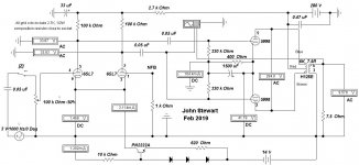
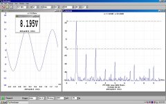
Playing around with R9 gives you very nice effect.
Spectrum of signal getting close to triode one.
No reason to go over 6K. Not good at all. I stopped at 5K8.
Output impedance of transformer is 4Ohm but I use it with 8 Ohm speakers.
Also make sense. At least for me 🙂
Playing around with R9 gives you very nice effect.
Spectrum of signal getting close to triode one.
No reason to go over 6K. Not good at all. I stopped at 5K8.
Output impedance of transformer is 4Ohm but I use it with 8 Ohm speakers.
Also make sense. At least for me 🙂

Just forget to mention
Playing around with R9 gives you very nice effect.
Spectrum of signal getting close to triode one.
No reason to go over 6K. Not good at all. I stopped at 5K8.
Output impedance of transformer is 4Ohm but I use it with 8 Ohm speakers.
Also make sense. At least for me 🙂
Yes, that does make sense. Varying the value of R9 affects the balance of the driver stage outputs. More driver imbalance = more H2 content.
It also makes sense that you're using 8 ohm speakers on the OPT 4 ohm secondary tap. That effectively makes the OPT primary look more like 4k ohms, which is pretty much textbook for push-pull 2A3 or similar. (12AV5GA-triode has electrical characteristics close to 2A3.)
The NFB loop on the SE amp is interesting. C5 will need to be a big capacitor (2uF 600V).
Why the 6.5k ohm primary? That's a quite high value for 12AV5GA-triode.
I've heard a couple of SE amps made with UL, pentode or beam tetrode outputs that didn't use NFB. I didn't like that flavor. Kind of 'raw' and 'brash' sounding.
During late winter & spring of 2019 I tried several experimental versions of amps essentially like this one.View attachment 1062248
Pretty easy to assemble and make it work.
Not bad idea for reliable and nice amp.
Made one for myself lately
But the drivers were all differential, some with tails to -150V, others had an NPN tail.
All built on an inverted cake tin, so named the Betty Crocker special. I wouldn't do a cake tin again, very inconvenient.
The pin outs of 6SN7, 6BX7, 6BL7 & 5998 are the same so it was possible with minimal change to check the performance of all.
All the test results are here on DIY. More recently the Betty Crocker has been rewired for a pair of 6EA7/6EM7s.
All of the tests are in Class A while the Pd is not exceeded. With these conditions the 6SN7 was good for about One Watt.
The 6BX7 & 6BL7 managed 3W. The 5998 did >10W at clipping. I used a lab supply for power.
Attachments
With 1mOhm right at the entrance..... I already have some doubts.Be easier if you had only 1 driver stage.
dave
Yes, 12av5 is the poor man 2a3 🙂It also makes sense that you're using 8 ohm speakers on the OPT 4 ohm secondary tap. That effectively makes the OPT primary look more like 4k ohms, which is pretty much textbook for push-pull 2A3 or similar. (12AV5GA-triode has electrical characteristics close to 2A3.)
As for primary impedance on SS, I used the 8K/4ohm transformer.
I should be more careful before publishing, sorry.
I was playing a bit with primary impedance and with 8K I've got sound I like most.
Very personal opinion, and probably questionable.
Last edited:
You are right. Sound is a bit rough.I've heard a couple of SE amps made with UL, pentode or beam tetrode outputs that didn't use NFB. I didn't like that flavor. Kind of 'raw' and 'brash' sounding.
The story is: I've got good deal on 12av5 and 6s7b 🙂 and after getting it started to discover what I can really get out of it. Both valves resonably good and capable. And I did 3 different designs. Two SS and one PP.
The second SS does have SRPP at first stage and also a little bit sophysticated NFB. What I like about it most of all it is very stable and reliable.
Yep, you could convert it to floating paraphase. 😀 😉Yep you are right, easy to fix thou.
dave
We turned paraphase in a big Chinese amp to a proper CCS LTP, made a sugnificant improvement.
dave
dave
Just jerking your chain Bro. 🙂We turned paraphase in a big Chinese amp to a proper CCS LTP, made a sugnificant improvement.
dave
- Home
- Amplifiers
- Tubes / Valves
- Nice and easy PP