Hi Guys,
Apologies in advance for the long read!
I have an old Arcam DVD player that has been connected up to my system for many many years and hasn't been used in a long while. When I went to use it for some cd playback I get a hum on the analogue outputs that rises with volume from the amp. The digital output via coax is whisper quiet.
I downloaded the manual and thought that the AV board smoothing caps might of dried out so replaced those along with the adjacent voltage regs, made no difference at all.
So next I took a look at the PSU and visuslly it all looks good.
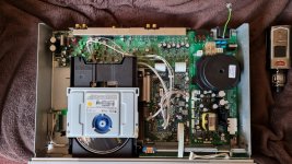
I then started to unplug all the power cables from the board one at a time untill the PSU was stand alone and I still had the hum. Image attached shows both boards completed isolated. I then disconnected the ground wire from the chassis, now all is quiet. The PSU is grounded to the PCB from the earth pin through the suppressor caps to the transformer, there is also a grounding path through the board so when screwed to the chassis the chassis is grounded.
So my question is what do you think this could be, my guess is its RF from the toroidal transformer. Do you think replacing the 4 suppressor caps and common mode choke would fix it?
I don't really want to use it whith out the additional earth to the chassis.
Apologies again for the long read.
Many Thanks
Apologies in advance for the long read!
I have an old Arcam DVD player that has been connected up to my system for many many years and hasn't been used in a long while. When I went to use it for some cd playback I get a hum on the analogue outputs that rises with volume from the amp. The digital output via coax is whisper quiet.
I downloaded the manual and thought that the AV board smoothing caps might of dried out so replaced those along with the adjacent voltage regs, made no difference at all.
So next I took a look at the PSU and visuslly it all looks good.
I then started to unplug all the power cables from the board one at a time untill the PSU was stand alone and I still had the hum. Image attached shows both boards completed isolated. I then disconnected the ground wire from the chassis, now all is quiet. The PSU is grounded to the PCB from the earth pin through the suppressor caps to the transformer, there is also a grounding path through the board so when screwed to the chassis the chassis is grounded.
So my question is what do you think this could be, my guess is its RF from the toroidal transformer. Do you think replacing the 4 suppressor caps and common mode choke would fix it?
I don't really want to use it whith out the additional earth to the chassis.
Apologies again for the long read.
Many Thanks
Attachments
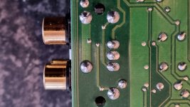
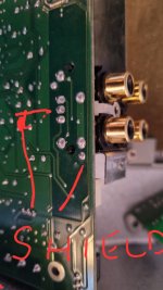
If everything is disconnected power-wise and you still have hum/buzz... look at the RCA pins' soldering to PCB.
Also, how is this metal RF protection case connected to the players' common (chassis) ground?
Once the unit is assembeld back in full, does that RF protection case sit at the mains IEC ground pin potential?

Also, how is this metal RF protection case connected to the players' common (chassis) ground?
Once the unit is assembeld back in full, does that RF protection case sit at the mains IEC ground pin potential?
Thanks for your reply extreme, I have touched up the pins on the rca outputs with fresh solder. I've tested continuity between the Earth pin and shield striped down and there's no direct link. The rear panel screws directly to the shield so grounding through chassis once assembled. It's a 20 year old unit that up until now has been on point, that's why I think it's a failed component. However my experience is limited.
Do you think a failed choke or supressor could case this?
Thanks again appreciated
Do you think a failed choke or supressor could case this?
Thanks again appreciated
Do you think a failed choke or supressor could case this?
My understanding is that you hear the buzz/hum when the player is not powered - that's how you did the test...? Usually, that means there's a problem with grounding somewhere. I suggest you put everything back together and try the same test again. Make sure the screws are tightening the panels / IEC ground pin correctly, i.e. make sure the ground uniformity is good.
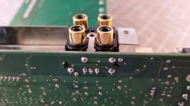
Heck, the RCA socket may have corroded (after 20 years) so much that the interconnects middle RCA pin does not make good contact with the player's RCA socket...
The RCA sockets may have a muting output relay that will short the RCA hot to the ground when the player is OFF. If this is the case, you should not hear any buzz/hum if the RCA connections are okay, if the RCA cables are okay, and if the RCA's are soldered correctly to the PCB.
Taking well lit, in-focus detailed photos of that RCA PCB (surrounded by that metal shield) will tell us more... also, you should try to obtain the service manual to check how the muting circuit is done.
If the player starts to buzz/hum when you turn the power on, then you may have a problem with power supplies/power rails regulation... or other electronic parts on the PCB... somewhere. Service Manual shows what waveform to expect, and where exactly.
Good luck.
Last edited:
Hi
The buzz is heard as soon as the mains is plugged in to the power supply. With all internal cables disconnected so both boards are completely detached from each other a hum is still the same with the short earth strap connected to the chassis. Once the earth wire is disconnected the hum goes away. So this must be 'through the air' as nothing is connected. Looking at the drawing the choke and suppressor caps as well as the front panel power button are the only things to powered in this state. I have attached an image of the socket as well as the service manual. I have swapped out RCA cables and also tested on another amp.
Thanks again.
Attachments
Make sure the amplifier power cord and the DVD player power cord are plugged into the GPOs that have the same ground connection.
Assemble everything together, make sure the screws are tight and power up the unit. See what happens.
Check the RCA sockets' common potential vs. chasses potential... see if you read zero ohms. Check the result vs. what the schematics is saying, i.e. the RCA sockets common (outer metal ring) might be AC coupled to DVD chassis.
Just a thought.... it may not be the DVD payer at all.... to check, plug the DVD player into a different amplifier input; one that works okay with a different source.
It is certainly the DVD player I've tried different interconnects on different inputs and on another amplifier.
All reassembled there is zero ohms between the center pin to chassis and zero ohms between the center pin and the outer ring. There is around 100mv ac between the center pin and earth. Even when switched off at the front switch.
What do you reckon? Drawing attached in previous post.
Thanks again
All reassembled there is zero ohms between the center pin to chassis and zero ohms between the center pin and the outer ring. There is around 100mv ac between the center pin and earth. Even when switched off at the front switch.
What do you reckon? Drawing attached in previous post.
Thanks again
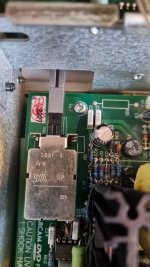
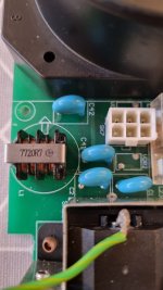
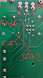
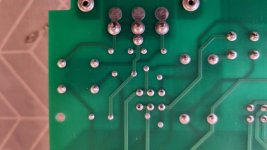
Remove the wires marked with a red X. Still buzzing/humming? If there's still buzz, your Y capacitors replacement did not work. Please provide the photos of both sides of the PCB where the capacitors are soldered to it.
Did you also replace the C41 and C42 as well? I need to see the photos of all Y capacitors. Post the choke photo as well.

How is that mains switch (metal?) case connected to the ground (see blue question mark). Post some photos, please.
The output RCA block (metal cage) photo you posted is just an RCA PCB eyelets' soldering.... I need to see how that metal cage, surrounding the output RCA PCB, is connected to the chassis. Also, how is that PCB coupled to that cage??? DC coupling, (mounting screw eyelet copper pad in direct contact with the metal cage)?, or AC coupling (there's an SMD capacitor between PCB ground and metal cage)?
The mains cable stayed plugged in for a long time, and the X and Y capacitors started to leak (actually, there are no X's, just Y's).... this is the most likely root cause of your problem.
NOTE: If you lift (desolder) only one side of each (all 4 of them) Y capacitors, and the buzz goes away....
Did you also replace the C41 and C42 as well? I need to see the photos of all Y capacitors. Post the choke photo as well.
How is that mains switch (metal?) case connected to the ground (see blue question mark). Post some photos, please.
The output RCA block (metal cage) photo you posted is just an RCA PCB eyelets' soldering.... I need to see how that metal cage, surrounding the output RCA PCB, is connected to the chassis. Also, how is that PCB coupled to that cage??? DC coupling, (mounting screw eyelet copper pad in direct contact with the metal cage)?, or AC coupling (there's an SMD capacitor between PCB ground and metal cage)?
The mains cable stayed plugged in for a long time, and the X and Y capacitors started to leak (actually, there are no X's, just Y's).... this is the most likely root cause of your problem.
NOTE: If you lift (desolder) only one side of each (all 4 of them) Y capacitors, and the buzz goes away....
Last edited:
Thanks for taking the time to read, post and look through the schematics, appreciated.
Yes the power has been connected 24/7 for 20 years! I did not replace the ceramic caps on the power supply. Initially not realising that the hum was there even when switched off I replaced the caps on the AV board C1 and C3 pre the outputs. The switch is metal cased and is grounded through a pad on the board marked REF. The red Xs are not wires they are tracks on the board. The sheild is soldered to the board but goes no where and is earthed through the back panel. I've attached some photos that you ask for, let me know if you would like others or clearer ones.
Thanks again for ya help.
Attachments
Sorry didn't answer your question regarding the scart. Nothing is attached to the scart and never has been, video is connected via the component out's. Also forgive my limited knowledge not sure what you mean around the AC/DC coupling of the cage. Which SMD goes between ground?
There are a few approaches....
- you could cut the PCB tracks (Exacto-knife) that I marked with a red X and try that.... if there's no buzz - replace the Y caps and possibly the choke. This approach will undeniably isolate the problem to the IEC mains connector, 4 x Y caps and possibly the choke. Once done with replacements, just scrape the lacquer and solder the tracks to ensure conductivity is re-established. While at it, make sure that the conductivity check between the switch lugs (4 pins) and its metal case, shows infinity (best is to remove the switch from the PCB for this test). Use the Solder-pult.
- you could just go ahead and replace the 4 x 3.3uF Y-rated capacitors. Make sure they are at least rated for 250V AC. You could also replace the L1 choke.
If you are not comfortable working with these parts (that handle mains voltage), take the player to a technician to do it for you.
... heck, you could just remove all 4 capacitors (Y-rated) and the choke (bridge out the choke pins 1 and 2, and 3 and 4) - just for the test purposes. Make sure you are bridging the right pins !!!! otherwise, the mains fuse in your distribution board will blow out / trip. If the buzz disappears, get the replacement parts for caps and choke.
Once again, if you are uncertain of what I'm saying here.... take the player to someone who can do these things for you.
Last edited:
Thanks for getting back. I think I'll replace the 4 caps 1st, if it's still humming I'll do the choke. It's not worth paying to have it done, it cost me £1000 20years ago and is now only worth around £100 on ebay maybe less. In the near future I'll probably sell it on reluctantly due to remodelling of the room. I'll get back to you in a couple of days once I've replaced the Y caps.
Thanks
Thanks
Think I've hit a brick wall now, very frustrated! Today I've removed the choke and C1 and C2 from the board so the socket is sitting on its own and it's still humming when the earth cable is connected to the chassis.
Any other ideas, now thinking it can't be the PSU?
Any other ideas, now thinking it can't be the PSU?
Looked back at your post re smd from rca socket, looks like there's a hole in the ferrite bead on the AV board L16 between the outer ring and ground! Do you think that would cause it to hum?

Your EMC ground, and your RCA-out shield, were sitting at vastly different potentials...
EMC ground: S-Video OUT shield, fixing holes to case (which probably means the mains IEC ground as well.... but you should trace this to confirm).


EMC ground: S-Video OUT shield, fixing holes to case (which probably means the mains IEC ground as well.... but you should trace this to confirm).
Thanks for your reply, I've ordered some ferrite beads will let you know once its in and all checked out. Fingers crossed it sorts it out!
Took a week to get the ferrite beads as I didn't have the experience/know how to check for compatable SMD. So I got hold of some originals from Germany. Removed the bead, cleaned the pads, stuck the new one in and BINGO all is so so quiet unbelievably so!
Thanks extreme for sticking with me on this, think I made it more complicated than it should of been but we got there in the end, hopefully the post might help someone else.
Many Thanks you've been so helpful
Thanks extreme for sticking with me on this, think I made it more complicated than it should of been but we got there in the end, hopefully the post might help someone else.
Many Thanks you've been so helpful
- Home
- Source & Line
- Digital Source
- Arcam DV88+ Hum on analogue outputs