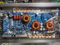
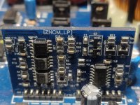
Am currently rebuilding a blown DS18 5k. The power supply and output section both need repair. Power supply used IRFP064N with 22ohm gate resistors and outputs are IRFP260M and I will be replacing all of the above. The PS FET driver section sustained some damage and I am unable to figure out the correct resistor values for some of the locations. Also need to know if the transistors I have on hand will work as substitutes for what is in there.
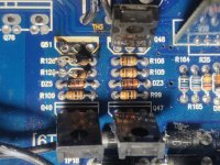
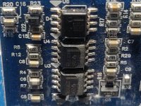
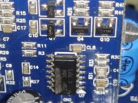
1) I need the resistance values for R128, R120, R109 and also the value for DZ5? I assume the row alongside is a mirror image and would use the same values and it also appears that the zener diodes survived but may change just to be sure.
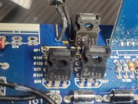
2) The drivers used in here are C2814/A_715. The two PNP drivers are disfigured so I can't make out the whole part number, but I am unable to find the NPN, and it's pairing locally. I have on hand C2690/A1220 and B631K/D600K if either of those pairs are substitutable.
1) I need the resistance values for R128, R120, R109 and also the value for DZ5? I assume the row alongside is a mirror image and would use the same values and it also appears that the zener diodes survived but may change just to be sure.
2) The drivers used in here are C2814/A_715. The two PNP drivers are disfigured so I can't make out the whole part number, but I am unable to find the NPN, and it's pairing locally. I have on hand C2690/A1220 and B631K/D600K if either of those pairs are substitutable.
Attachments
A1715
If this is the PS, you don't need high-voltage drivers. The BD139 and BD140 would work.
The left and right columns should be identical.
470
180
9.1 or 10vZ
10k
If this is the PS, you don't need high-voltage drivers. The BD139 and BD140 would work.
The left and right columns should be identical.
470
180
9.1 or 10vZ
10k
I don't have BD139/140. Would any of those I have work, or would they be too much of a load on the driver controls?
They will work but are both in short supply so it would be a shame to waste them if you have something else.
MJE172/182?
I found the datasheet. The replacements you listed would be low on the current rating but I'd expect them to work.
http://www2.kec.co.kr/data/databook/pdf/KTA/Eng/KTA1715.pdf
MJE172/182?
I found the datasheet. The replacements you listed would be low on the current rating but I'd expect them to work.
http://www2.kec.co.kr/data/databook/pdf/KTA/Eng/KTA1715.pdf
Last edited:
Have gotten the power supply put back together and getting a solid ±80v of rail. Want to know how I can check the output section before populating with the new outputs. Unsure if this amp is supposed to show gate drive without outputs in. Have 5v of gate drive on the - outputs and no drive on the + outputs...
These are what the output gate pads have on them:
- Output Pads
1) -75v
2) 38mv
3) -80v
+ Output Pads
1) 28mv
2) 80v
3) 38mv
These are what the output gate pads have on them:
- Output Pads
1) -75v
2) 38mv
3) -80v
+ Output Pads
1) 28mv
2) 80v
3) 38mv
Assume this is the audio driver board as the other one is Power Supply.
Attachments
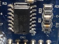
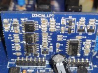
Measure the DC voltage between pins 11 and 13 of the 21844. If it's at or very near 0v, you'll need to supply the high-side with a supply voltage. I typically use a 9v battery.
I don'[t know what you have available but if you have a 9v battery, connect it across the header pins that are directly connected to pins 11 and 13 of the 21844 (negative terminal to pin 11). I recommend connecting to the header pins to make it easier. If it's easier to solder to the pins on the IC, do so.
Since I don't know this board well, I'd suggest inserting a 1 ohm, 1/8w resistor between the positive terminal of the battery and the connection to the driver board.
Since I don't know this board well, I'd suggest inserting a 1 ohm, 1/8w resistor between the positive terminal of the battery and the connection to the driver board.
I was reading up some other posts trying to get the answer and need some clarification. Do I remove the rectifiers and fully discharge the rail caps? Do I need to drive a signal into the amp to see gate drive? Do I need to connect a load to the speaker terminals?
Connecting a load will stabilize the high-side circuit, so... probably.
You should discharge the rail caps before soldering to prevent shorting anything to the rail voltage on the adjacent terminals.
You don't need to remove the rectifiers.
You will likely need to drive a signal into the amp to see the drive signal.
I don't have a diagram for the ZNCM amps so I can't be definitive on all of the answers.
I checked the resistance reading of the 21844 as instructed in the past and it read OK. I had enough outputs on hand that I could risk damage, hopefully not to damage the freshly rebuilt power supply. I installed the outputs and had gate drive to both high and low side and have audio at the speaker terminals.
The amplifier plays clean bass when tested in the car but the only oddity is that it seems to be lower output than it should be or just requiring much higher input gain to produce adequate output. The gain control in this amp has to be turned up VERY high in order to produce the same level of output that all other amps swapped in (Orion 2500.1dz/Stetson EX3000) produce with the gain very low.
What can I check/change to figure out if there is a problem?
Crossover and bass boost settings could make a difference.
Is this your amp or for a customer?
How much signal do you have to drive into the amp to get to clipping at the minimum and maximum gain?
Are there any markings on the end plate for the gain pot?
Is this your amp or for a customer?
How much signal do you have to drive into the amp to get to clipping at the minimum and maximum gain?
Are there any markings on the end plate for the gain pot?
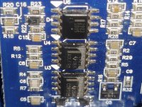
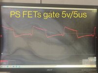
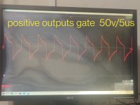
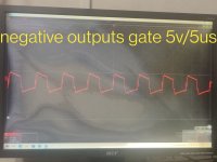
Back to this one. Amplifier is functioning and has output but goes into protection when turned up. Was tested in the vehicle at the time so I have it on the bench right now. Amp pulls my 13.68v supply down to 13.10v which doesn't seem excessive but the output inductor gets very hot and the waveforms are not crispy clean. I am posting scopeshots of the PS driver IC output, PS FETs gate leg and the + speaker terminal.
Attachments


- Home
- General Interest
- Car Audio
- Blown DS18 PRO-KA5000.1D