I have a friend with hum problems in his phono preamp, attached schematics.
If someone can help me to simulate with LTSpice to know wich values of voltage are correct to measure will be very helpfull.
TIA
If someone can help me to simulate with LTSpice to know wich values of voltage are correct to measure will be very helpfull.
TIA
Attachments
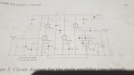
The heater supply of the ECC83's and the ECC81 is not earthed in the schematic but maybe the heater supply is intended to float. The maximum cathode to heater voltage of the ECC81 is 90 V. I estimate the anode voltage of the preceding ECC83 to be about 118 V. The cathode of the ECC81 sits a little bit above this 118 V. So with the heater supply earthed, the maximum cathode to heater voltage of 90 V for the ECC81 would be violated.
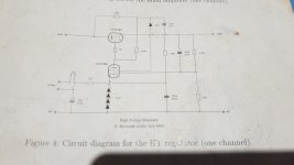
The heater supply of the ECF80 seems odd to me. It looks like it is elevated to 51 Vdc. The cathode of the ECF80 sits at 300 V. The maximum cathode to heater voltage of the ECF80 is 100 V. So if the heater would really sit at 51 Vdc, than this maximum would surely be violated. Maybe the 22K resistor plays some role I don't understand. But even if that 22K resistor would 'allow' the dc-voltage of the heater supply to rise to somewhere half way in between 51 V and 300 V, so to about 175 Vdc, still the maximum cathode to heater voltage of 100 V of the ECF80 would be violated.
But maybe the "51V" at the four zeners means 51 V for each zener instead of 51 V in total.
Last edited:
The heater supply of the ECC83's and the ECC81 is not earthed in the schematic but maybe the heater supply is intended to float. The maximum cathode to heater voltage of the ECC81 is 90 V. I estimate the anode voltage of the preceding ECC83 to be about 118 V. The cathode of the ECC81 sits a little bit above this 118 V. So with the heater supply earthed, the maximum cathode to heater voltage of 90 V for the ECC81 would be violated.
The heater supply of the ECF80 seems odd to me. It looks like it is elevated to 51 Vdc. The cathode of the ECF80 sits at 300 V. The maximum cathode to heater voltage of the ECF80 is 100 V. So if the heater would really sit at 51 Vdc, than this maximum would surely be violated. Maybe the 22K resistor plays some role I don't understand. But even if that 22K resistor would 'allow' the dc-voltage of the heater supply to rise to somewhere half way in between 51 V and 300 V, so to about 175 Vdc, still the maximum cathode to heater voltage of 100 V of the ECF80 would be violated.
The ECC81/3s run on 12.6 volts DC referenced to 0volts. The ECF80 has its own isloated heater supply.
Check to see if the hum stops with the inputs shorted to ground. If it does, check the phono wiring and make sure the deck chassis is earthed.
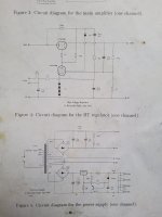
The 6.3 V supply for the ECF80 in the schematic of the power supply is also referenced to 0 V, but it obviously should not be connected to the 0 V of the B+ supply. So the "0 V" at the 12.6 Vdc doesn't say much.
Yes the hum stops with inputs sorted. Could be the TT GND?The ECC81/3s run on 12.6 volts DC referenced to 0volts. The ECF80 has its own isloated heater supply.
Check to see if the hum stops with the inputs shorted to ground. If it does, check the phono wiring and make sure the deck chassis is earthed.
Just my 2 cent: try the wire from TT metal parts (for example bearing) to phono preamp grounding point (case or individual grounding point).
Sample:
https://houseandbeyond.org/how-to-ground-a-turntable/
Sample:
https://houseandbeyond.org/how-to-ground-a-turntable/
Some unfinished business:
The 4 zeners are 51 V each (so 204 V in total) because the voltage divider formed by the 1M and 470K resistors make the control grid of the pentode section of the ECF80 sit at about 204 V. So the heater supply for the ECF80 is OK.
But if the 12.6 Vdc heater supply is grounded, violation of the maximum heater to cathode voltage of the ECC81 is still likely.
Last edited:
Only if the ECC81 is faulty.But if the 12.6 Vdc heater supply is grounded, violation of the maximum heater to cathode voltage of the ECC81 is still likely.
The potential divider holds the warm up grid voltage low and the cathode will follow the voltage divider some 330k and 39k. Roughly speaking 15% of the HT voltage of 300volts. 45volts maximum.
Not a problem.
Wrong again.
The 330K resistor (= the anode resistor of the preceding 1/2 ECC83) and the 39K resistor (= the cathode resistor of the 1/2 ECC81) do not form a potential divider since they are not connected to each other.
Like I already wrote in post #2: I estimate/calculate the anode voltage of the preceding 1/2 ECC83 to be around 118 V. The cathode voltage of the 1/2 ECC81 will settle a little higher than this 118 V. This would mean that if the heater supply of the ECC81 is earthed, the maximum cathode to heater voltage of the ECC81 will be violated with more than 28 V.
Impossible AC values, or/and totally incompetent measuring!
If he shorted the phono input, measurable (handheld voltmeter?) AC component cannot occur.
If it present, one of the active parts oscillates.
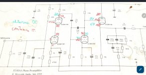
BTW each "lower" tubes cathode MUST be -at about- 1V DC and grid at 0V DC.
If he shorted the phono input, measurable (handheld voltmeter?) AC component cannot occur.
If it present, one of the active parts oscillates.
BTW each "lower" tubes cathode MUST be -at about- 1V DC and grid at 0V DC.
Last edited:
If the dc voltage at the cathode fo the ECC81 is indeed 145 V, and if the heater supply for the ECC81 is grounded, the maximum cathode to heater voltage of 90 V of the ECC81 would be exceeded with 55 V.
A possible solution is to elevate the heater supply for the ECC83's and the ECC81 to 55 Vdc.
An other solution is to replace the ECC81 with a 12AZ7. In that case the heater supply can stay grounded. The characteristics of the 12AZ7 are practically identical to those of the ECC81, but the maximum cathode to heater voltage of the 12AZ7 is 200 V. The heater current of the 12AZ7 at 12.6 V is 225 mA (against 150 mA for the ECC81). But I don't think the extra current of only 75 mA is a problem (675 mA against the original 600 mA).
Thanks Bela.Impossible AC values, or/and totally incompetent measuring!
If he shorted the phono input, measurable (handheld voltmeter?) AC component cannot occur.
If it present, one of the active parts oscillates.
BTW each "lower" tubes cathode MUST be -at about- 1V DC and grid at 0V DC.
No.Bela DC voltages are OK?
At these grid-cathode voltages (3V and above) and these low anode-cathode voltages (100..150V) all ECC83 is closed.
IMHO the "measuring device" has not enough high input impedance, so at these low currents (below 1mA) in phono amplifier the grid voltage measuring detect false values.
The cathode voltage measuring (which is represents cathode current on cathode resistor) provides enough information about that tube working or not.
- Home
- Amplifiers
- Tubes / Valves
- Phono preamp hum