IRFZ44R blown in one of this amps' two power supplies.
I pulled out ALL IRFZ44R in both supplies. Cleaned up the board and replaced gate resistors. I'm finding terrible looking drive signal on the gate pads of the side which blew. Pulled driver transistors. Signal coming from the IP3525 (SG3525) pins 11 and 14 looks like a bunch of mess. Also the IP3525 does not have clear osc pin 4.
1. 0.031
2. 5.13
3. 0.296
4. 0.517
5. 2.261
6. 3.897
7. 2.607
8. 4.5
9. 5.21
10. 0.031
11. 5.04
12. 0.031
13. 13.05
14. 3.820
15. 13.05
16. 5.13
I'll post some images of both IP3525 OSCs next
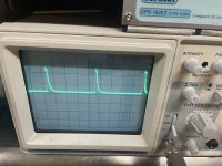
OSC images. First image is from the good ip3525, OSC. 2v/div both at 2uS. Honestly, the output of the 'bad' IP3525 looks very similar to OSC at fet gates. Signal on the GOOD IP3525 output is perfectly square.
Attachments
Last edited:
I dont have any spare IP3525 (Wide SG3525 SOIC) in stock. Has this IP3525 failed? None of the PS drivers measure failure.
Here is what Im getting on the pins of the PWM driver board.
1. 0.066
2. 2.581
3. 0
4. 0
5. 0.9
6. 0.030
7. 0.030
8. 0.030
9. 11.78
10. 0.296
11. 5.38
12. 4.38
13. 13.03
14. 4.38
15. 5.13
1. 0.066
2. 2.581
3. 0
4. 0
5. 0.9
6. 0.030
7. 0.030
8. 0.030
9. 11.78
10. 0.296
11. 5.38
12. 4.38
13. 13.03
14. 4.38
15. 5.13
I think I figured out that my scope wasn't locking on correctly; although there are still issues with this amp.
I put an IRFZ44 into each PS bank. Powered and the amp draws 2.4A with bias CCW on all ch.
Next,
U701 LM358
1. 0.180
2. 0.180
3. 0.015
4. 0.015
5. 2.566
6. 2.606
7. 0.213
8. 12.87
The amp passes audio on ALL channels, but CH1-4 have skewed rail voltages and clips bottom wave very soon. Front and Rear of this amp have different voltages entirely as I believe the amp has different ratings per set, but neither set are even referencing secondary ground.
Referencing non bridging terminals of classAB channels
Front channels' rails: +38.5v and -26.7 <- Tends to float a bit further away from even then stops here
Rear channels' rails: +33.5v and -17.5v <- Tends to float a bit further away from even then stops here
5th ch: +60v (+30v on terminals) <-Rock solid. CH5 is working great.
Regulated: +-14vDC
Resistance between components:
NBSPKT to B-: 0 ohms. Either to RCA shields: 1+Million ohms.
Also, one of the 3w 4ohm snubber near T900 transformer burns up in smoke if I dont remove it. The 104J100 cap connected to that snubber I found blown apart and replaced but the resistor still smokes.. Transformers in this amp are different sizes. Both transformers' secondary ground are connected to B- and NBSPKT.
Would T900 be shorted? It looks OK on the pcb. Twisting hard doesn't change anything.
What's the gate voltage on the muting transistors?
Are all of the 0.15 ohm source resistors within tolerance?
Are all of the 0.15 ohm source resistors within tolerance?
J111 gates go from 0v to -13.8vDC after about 4 seconds.
All source resistors are OK. This amp did not suffer any output transistor failures.
The amp passes audio.
The bottom clips on output which is caused by signal hitting the lower rail well before it hits the upper. Rail voltage being skewed does not make sense.
All source resistors are OK. This amp did not suffer any output transistor failures.
The amp passes audio.
The bottom clips on output which is caused by signal hitting the lower rail well before it hits the upper. Rail voltage being skewed does not make sense.
Do you have a bad connection on a busbar?
Where are you losing voltage between the output of the rectifier and the source leg of the FETs?
If there is no loss, are the two internal diodes of the negative rectifiers OK?
Where are you losing voltage between the output of the rectifier and the source leg of the FETs?
If there is no loss, are the two internal diodes of the negative rectifiers OK?
I measured those number right at the rectifiers' center legs. I was thinking of changing them all out seeing as the center legs are not precisely clean voltage as I would expect. Center legs of the rectifiers are showing some stray signal from the transformer. Possible leakage.
I checked busbars. There are a lot of them.
I will report back after swapping rectifiers.
I checked busbars. There are a lot of them.
I will report back after swapping rectifiers.
Replaced all rectifiers and not any better.
Looking back at the ps and pwm, it would appear that the pwm is lopsided so to speak. Like it’s driving slightly off kilter creating more positive rail voltage. The fets are not heating.
Looking back at the ps and pwm, it would appear that the pwm is lopsided so to speak. Like it’s driving slightly off kilter creating more positive rail voltage. The fets are not heating.
In an amp that has positive and negative rails, the positive and negative are produced by the same pulses, except in a few amps like the Alpine MRV-1507. Post a waveform of what you're seeing.
If you measure continuity from the input legs of one rectifier input to all of the other inputs, do you read 0 ohms?
If you measure continuity from the input legs of one rectifier input to all of the other inputs, do you read 0 ohms?
All 5 rectifier input legs ready 0 ohms between each other.
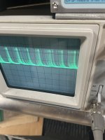
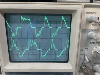
Here is a photo with a probe on each fet center leg of the smaller PS connected to T900. 10vDiv moved both trace lines exactly +-20. Its actually very hard for my scope to lock on to this PSs' signal as its fluctuating quite a lot more than desired.
Why would one of T900's snubber resistors instantly go to 600F and smoke and also explode the cap connected in series? I have that one removed still.
Attachments
Lower the 12v supply voltage as low as the amp will allow. Does that give you better output to the audio circuit?
Aren't the sub and rear channels driven from the same transformer?
Aren't the sub and rear channels driven from the same transformer?
Actually lowering the supply voltages causes the signal on the PS fets to become more dynamic and 'regulated' looking down to 10.2v where the amp then shuts down. Most amps lowering supply voltage will cause the PS to run full duty cycle. Not this amp. It gets harder to lock onto the drive signal just before shutdown.
Yes the sub and rear channels are both connected back to T900 transformer.
Yes the sub and rear channels are both connected back to T900 transformer.
So, are you saying that the rail voltage is precisely as expected with the lower 12v supply voltage?
- Home
- General Interest
- Car Audio
- JL 500/5 one PS failure