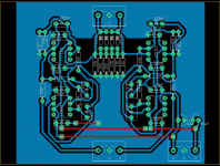
Recently I build this MC Head amp using an own PCB design. It sounded pretty good I think so far, except for a quite loud hum. I tried everything so far, moving the PSU out of the box (no ripple voltage btw), different grounding and so on. The noise sounds like 50 Hz hum and it's louder without the turntable connected so I believe that it must be picked up by the PCB from its surroundings, even though its in an grounded metal box.
Datasheet for LT1115 says that the grounding of PCB is indeed important, suggesting single point grounding. Looking at the PCB design I know realize that I may have created a "ground loop", or is this possible? Since I can't figure any other way than make a new PCB to decrease the hum, so what else should I change? Adding a extra layer just for ground?
Datasheet for LT1115 says that the grounding of PCB is indeed important, suggesting single point grounding. Looking at the PCB design I know realize that I may have created a "ground loop", or is this possible? Since I can't figure any other way than make a new PCB to decrease the hum, so what else should I change? Adding a extra layer just for ground?
Attachments
If you have grounds coming from both the MC power supply and the amplifier this would give you a loop .
The PSU is an wall mount ac-ac adapter that supplies the PCB within the amp with ac, so no safety ground is involved that can cause a ground loop.If you have grounds coming from both the MC power supply and the amplifier this would give you a loop .
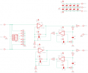
Schematics for the PSU and amp is available at the page I linked. But here's the schematic attached that the board is based on anyway.
Attachments
The LT1115 is not unity gain stable. It may be oscillating with 100% feedback at HF by C15, 16. When oscillating at HF, a hum may be heard. Try removing C15, 16 and see if the hum disappears.
I would be surprised when C15/C16 are the cause of the hum.
You could as a test replace the power supply by two 9V batteries to see if the hum is still there, if not, your power supply is causing the hum.
The other thing you can try is to connect the casing of the head amp to Protective Earth, and from there via a 10R to your ananalog Gnd.
Final remark, nothing having to do with hum, is that I don’t understand R5 in the feedback loop.
This resistor produces more noise as the LT1115, so you better change R5 to 10R and R4 to 250R to gain 3dB in S/N.
Hans
The LT1115 is spec'd to drive 600 ohms - not sure it handles a 260 ohm load well, though perhaps this isn't an issue for low-level signals.
Correct, no issue at all with these low level signals.The LT1115 is spec'd to drive 600 ohms - not sure it handles a 260 ohm load well, though perhaps this isn't an issue for low-level signals.
Hans
Your ground plane is a "radiator" in the sense of antenna, picking up mains radiation. It's like the stock PCB of the "Pearl II" for which hum in an omnipresent issue!
You may also pick up mains radiation from the umbilical connecting the power supply to the PCB.
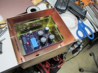
Now that the board is burned, you can remedy the situation by putting the PCB into a small candy or cookie tin, best if it's steel. You could go the extra mile as Linear Tech did in this application note by having a clamshell made of PCB material inside a cookie tin. Obviously, yours is going to be a lot smaller. (Edit, I include a pic of a very low noise measurement amplifier which uses an IF3602 JFET -- it is triple shielded.
You may also pick up mains radiation from the umbilical connecting the power supply to the PCB.
Now that the board is burned, you can remedy the situation by putting the PCB into a small candy or cookie tin, best if it's steel. You could go the extra mile as Linear Tech did in this application note by having a clamshell made of PCB material inside a cookie tin. Obviously, yours is going to be a lot smaller. (Edit, I include a pic of a very low noise measurement amplifier which uses an IF3602 JFET -- it is triple shielded.
Attachments
I thought I had it saved in my "Noise" stack, but I guess not. One of those articles using several ADA4898 to measure noise.Do you have a link for that Linear Tech box?
- Home
- Source & Line
- Analogue Source
- MC Head Amp hum, bad PCB design?