In a 2 stage SE amp, both plate voltages are both coming off of one B+ source as simple split wires going into the two tubes. Given that the plate voltage for V2 is correct and comes directly out of the B+ without any problem; also given: the plate resistors are correct for both tubes and biasing for V2 is correct.
Problem: V1 needs a voltage dropping resistor and I can't seem to adjust for the correct plate voltage even with Ohms law.
Where is my mistake?
Do I also need to adjust the bias of V1?
Do I need another choke between the two tubes to "separate" their voltages?
Please advise.
Problem: V1 needs a voltage dropping resistor and I can't seem to adjust for the correct plate voltage even with Ohms law.
Where is my mistake?
Do I also need to adjust the bias of V1?
Do I need another choke between the two tubes to "separate" their voltages?
Please advise.
Vdrop across 195k is 195k * 2mA = 490V. That seems too high. It would leave only 550 - 490V = 10V across the top Ra. The top resistor has 28mA + 2mA = 30mA. With a Vdrop of 10V that resistor would be just 330 ohms. Ra2 (the lower, you haven't numbered them) would be 490 - 162 = 328 @ 28mA is ~12k.
Is that the operating point you want?
I'm also not sure I understand 'the plate resistors are correct for both tubes'. I see only one tube with plate resistors. Which one is V1, the right one? For this discussion it doesn't have any relevance as it is only AC coupled.
Jan
Is that the operating point you want?
I'm also not sure I understand 'the plate resistors are correct for both tubes'. I see only one tube with plate resistors. Which one is V1, the right one? For this discussion it doesn't have any relevance as it is only AC coupled.
Jan
Last edited:
Thanks for the math explanation. Because I have submitted this question, means that as a schematic it does not make sense to me to answer your question about the operating point. In fact this is not my schematic, nor my design. I consider myself more of a builder than a designer.
Perhaps if I rephrase my question: what is the value of the voltage dropping resistor on v1 required in order to take 550vdc from the b+ to make 162v on the plate of v1? Is it as I determined: 10k@ 125w? If not, why not?
Thanks.
Perhaps if I rephrase my question: what is the value of the voltage dropping resistor on v1 required in order to take 550vdc from the b+ to make 162v on the plate of v1? Is it as I determined: 10k@ 125w? If not, why not?
Thanks.
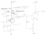
It's in my reply, step by step. Working backwards from the G2 to the RC junction it's 2mA through 195k= 390V, so that RC junction is 150 + 390 = 540V.
The top Ra carries 28mA + 2mA = 30mA over a voltage of 550 - 540 = 10V, so the top R is 10/30k = 330R.
Then basically over the bottom Ra you have 540V - 162V = 378 @ 28mA makes the bottom R 378/28= 13.5k.
I may have rounded it sloppy but that should be in the ballpark.
Jan
The top Ra carries 28mA + 2mA = 30mA over a voltage of 550 - 540 = 10V, so the top R is 10/30k = 330R.
Then basically over the bottom Ra you have 540V - 162V = 378 @ 28mA makes the bottom R 378/28= 13.5k.
I may have rounded it sloppy but that should be in the ballpark.
Jan
Well, since you put it that way!! Ok, I think I understand, except for one thing: from where did you get the 30k?
Ok, then are you suggesting that I change my cathode bias resistor from 7ohms to 330ohms, assuming I use a 10k on the voltage dropping resistor?
Is the cathode bias resistor on V1 really just 7 Ohms?
In general , changing the value of the plate load resistor to any significant degree will necessitate a corresponding change to the value of the cathode bias resistor for the same current.
If I've missed it then please excuse , but you should let us know what the tube types are. Looking at a data sheet will then give a better idea what the bias set-up should be.
yes, the cathode resistor is 7ohms@25w. The tube itself is a 7905.Is the cathode bias resistor on V1 really just 7 Ohms?
In general , changing the value of the plate load resistor to any significant degree will necessitate a corresponding change to the value of the cathode bias resistor for the same current.
If I've missed it then please excuse , but you should let us know what the tube types are. Looking at a data sheet will then give a better idea what the bias set-up should be.
That tube is a DHT. With 0,65A heater current there is a voltage drop of 4,55V on that 7Ω resistor and the heater supply is 6,3+4,55=10,85V DC. And the voltage on the cathode=heater goes from 4,55V one side (-F) to 10,95V other side (+F).
How about showing the heater circuit ?
Mona
How about showing the heater circuit ?
Mona
Looking at the 7905 data sheet , I would be inclined to start it at or near the given A1 operating point (Vp=approx 200, Vg2= approx 185VDC with cathode resistor of approx 200Ω for approx 35mA - provided your power supply is ok with the additional current) with a very roughly 5-7K load but that's just me.
How much gain you need from it depends entirely on the rest of the circuit . It really would be best to give complete circuit details up front as what you do with one tube depends on what it needs from the other tube and the power supply.
The value of the dropping resistor will depend entirely on what you choose for the 7905 circuit values so they need to be decided on first.
7R @ 30mA = 189milliWatt. What's with the 25W??yes, the cathode resistor is 7ohms@25w. The tube itself is a 7905.
Looking at the rightmost tube, that part of the circuit useless, doesn't do anything, output = zero.
Are you sure you have the circuit and all parts values correct? 30mA through 7V = 210mV which I think is too low for the operating point, but others may have more insight in that.
How did you come to the 7R, did someone set this up for you? Is this a circuit from the internet?
Jan

I understand that sometimes giving full disclosure can also expose one's understanding, or lack of it.
But get over that, we all started at ground level. Trying to hide things from fear of being thought a newbee is bad advise. Usually the first post shows proficiency level, and opening up can help get you forward fast.
Jan
But get over that, we all started at ground level. Trying to hide things from fear of being thought a newbee is bad advise. Usually the first post shows proficiency level, and opening up can help get you forward fast.
Jan
When providing a schematic, do remember to state whether the power supply is supplying a monoblock or two both left and right channels. Everything in the power supply prior to the connection to the second channel carries twice the current if it not a monoblock, so calculating the value of a dropping resistor may be out by a factor of 2 if you do not factor in what the whole circuit is.
kind regards
Marek
kind regards
Marek
- Home
- Amplifiers
- Tubes / Valves
- voltage dropping resistors