Hi All. I recently bought a Phono stage RIAA board from EBay. It does not work at all well. I then realised it was based on a published design by TEXAS Instruments of which I show the schematic. With a quick calculation you should see something very wrong with the overall gain apart from the response curve differing far too much because of rounded up component values. Who can spot the biggest mistake?

Attachments
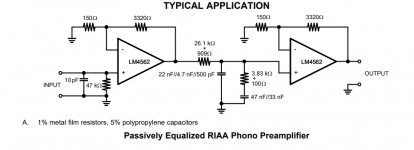
Just to make it more clear. The "rounded up" components I mentioned are on the actual board not on the schematic design. The pre-amp has a very drooping frequency response with little high frequency response.
If you tested this with a regular signal source you should get the RIAA curve which droops a lot above 1K and rises towards lower freqs.
Did you properly pre-eq the signal source to complement the RIAA curve?
I don't see any obvious problems (disregarding anything in the RIAA network, I haven't looked at that yet).
Jan
Did you properly pre-eq the signal source to complement the RIAA curve?
I don't see any obvious problems (disregarding anything in the RIAA network, I haven't looked at that yet).
Jan
I was intrigued with this although 'I don't do vinyl' 😀
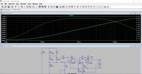
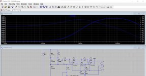
It doesn't quite look right to me, assuming I interpreted the values correctly. Have a play. There is an inverse RIAA at the front.
It doesn't quite look right to me, assuming I interpreted the values correctly. Have a play. There is an inverse RIAA at the front.
Attachments
But that's RIAA related I guess. Nothing on the gain as such I can see.
Is that anti RIAA correct? I also thought that the total range was 40dB, 20Hz @ +20dB and 20k at -20dB, ref 1kHz. Your network spans 52dB or so.
And 52dB - 40dB is the difference in the output response..
Also, this app note is quite old. Most probably they were using old standbys like the TL072, which has less HF response.
Jan


4562?
Newer chips exist...but the 20 uV/sec slew rate is right at the limit, higher will give distortion.
Feed back from negative rail of first stage too, maybe that is the problem.
Rail voltages not mentioned, that has a big affect on performance, I would like at least +/- 8 or up...rated as +/- 2.5 to +/- 17, so I would run it towards the higher side for better response.
With low supply volts it will sound muddy.
Try changing input and output impedances too.
I have used TL072 in a phono pre-amp, it was clean enough for The Eagles on vinyl.
Clear on the famous guitar duet about 4:23 into the song 'Hotel California', my version is 6:30 long....
Amp was a small Philips, 2030 and 1875 on either channel, Sony speakers.
This is some test, or you really have a problem?
Last edited:
Very many thanks for all your replies. Perhaps my post should have been more specific but "aboos" has spotted what the problem is...well done and thank you. He correctly says the gain is far too low. Each stage has an identical gain of 23db but the designer seems to have forgotten that the passive filter after the first stage attenuates the frequency response at 1Khz by approximately 20db to create the RIAA curve. The 2nd stage brings the gain back by only 23db which results in the overall gain of just 26db (23-20+23). The second stage needs to be around at least 40db to get an overall gain of around 43db at 1khz which is about the normal. It seems to me the producer of this assembled board has never tested it before marketing it on his shop. In practice I have to turn my preamp volume control to nearly maximum to get the same volume of a tuner input which has the volume control set to around the 10 o'clock position. As I also mentioned, it produces a very dull sound so something is wrong with the frequency response. However the shown schematic component values are correct when checked with an on-line "RIAA passive filter component calculator" so I can only imagine that the actual fitted components do not sum up correctly. I will have to remove them all to check. Finally, I wonder if there are any others here that might have made or bought this phono stage and had similar results? Many thanks for all your replies
In the days when this app note was written, 200mV was a reasonable sensitivity.
I wouldn't call this a 'problem', it is a design choice.
Jan
I wouldn't call this a 'problem', it is a design choice.
Jan
Is that anti RIAA correct?
Looks like I had a decimal point in the wrong place. Flat response now.

Also note that vinyl 0dB is up to 18dB below max signal level that can be cut. So for a 'hot' 12" you could end up still overloading the next stage. Rare, but happens.
Using a voltage controlled source together with a laplace transform to create the inverse RIAA source, the response is pretty well flat and would produce an overall output voltage of 270mv from a 5mV / 1kHz nominal moving magnet transducer. That's what would have been the norm back when the design was originally published.
Attachments
Agree with Bill, the overload margin at the higher end of the spectrum is pretty poor due to the flat response of the first stage. For a nominal input from the MM transducer of 5mV at 1kHz, the output at the top end frequencies will be 20dB higher and a further 18dB on top of that for a "hot" recording.
My calculation of each stage's gain results in 20 log(3470/150) = 27.3 dB. So, assuming a loss of 20 dB in the RIAA network, the overall gain is 34.6 dB. An input signal of 5 mV results in about 270 mV at the output. Replacing the 3320 Ω resistor in the 1st stage by 13 k would yield in an overall gain of 46 dB, which supposedly is sufficient.
Best regards!
Best regards!
- Home
- Source & Line
- Analogue Source
- Spot the mistake on this RIAA pre amp