Hi - about Rogers Developments UK HG88 Mk1
I'm wondering if you or anybody can help w/ the above. I've been working on this amp, where 1 channel was dead.
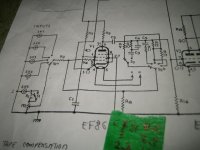
BTW, before the 2 ECL82's there's an ECC83, which has a mistake on the diagram:
Both sides have 1, 2, 3 for both Triode sections. A 2nd section must be numbered 6, 7, 8.
.Finally, I figured out that the #1 contact in this socket hasn't made contact w/ the tube's foot. I took out a contact from another 12 contacts tube socket, filed the sides & thickness - then inserted in the ECC83 socket. Re-soldered the 100K & coupling cap = problem solved.
While snooping around, I also found 2 leaking coupling caps in the said ECC83 & bchanged the Cathode 1K resistor(out of specs).
I think that the problem w/ the socket was caused by my taking in/out the ECC83 for testing on my "bible" AVO VCM3 tester(calibrated twice by me & 2nd time installed a re-manufactured 33uA Taut Band mtr from jacmusic in Germany. Of course I matched all the tubes via the AVO.
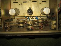
But, here's my real problem: this amp has rectifiers for the hi voltage - the originals have been paralleled by Silicons. From there - there're 2 power resistors(w/ the usual lytics(I paralleled w/ new due to hum) in a Pi network.
Unfortunately, I only have the CCT - but not the resistors values. Of course, I can read all the resistor values from their color coded bands.
BUT, the 2 filter power resistors(1 for each channel within the usual 2 lytics) - 1 was dead & the other has faded value on it. I measure 480 ohms, but that's an unusual value - perhaps 500?
Does anyone have a chart w/ the components values he can attach to his answer?
Thank you in advance, Dany, Toronto, Canada
I'm wondering if you or anybody can help w/ the above. I've been working on this amp, where 1 channel was dead.
BTW, before the 2 ECL82's there's an ECC83, which has a mistake on the diagram:
Both sides have 1, 2, 3 for both Triode sections. A 2nd section must be numbered 6, 7, 8.
.Finally, I figured out that the #1 contact in this socket hasn't made contact w/ the tube's foot. I took out a contact from another 12 contacts tube socket, filed the sides & thickness - then inserted in the ECC83 socket. Re-soldered the 100K & coupling cap = problem solved.
While snooping around, I also found 2 leaking coupling caps in the said ECC83 & bchanged the Cathode 1K resistor(out of specs).
I think that the problem w/ the socket was caused by my taking in/out the ECC83 for testing on my "bible" AVO VCM3 tester(calibrated twice by me & 2nd time installed a re-manufactured 33uA Taut Band mtr from jacmusic in Germany. Of course I matched all the tubes via the AVO.
But, here's my real problem: this amp has rectifiers for the hi voltage - the originals have been paralleled by Silicons. From there - there're 2 power resistors(w/ the usual lytics(I paralleled w/ new due to hum) in a Pi network.
Unfortunately, I only have the CCT - but not the resistors values. Of course, I can read all the resistor values from their color coded bands.
BUT, the 2 filter power resistors(1 for each channel within the usual 2 lytics) - 1 was dead & the other has faded value on it. I measure 480 ohms, but that's an unusual value - perhaps 500?
Does anyone have a chart w/ the components values he can attach to his answer?
Thank you in advance, Dany, Toronto, Canada
Does it differ greatly from the MkII? There is a list of components and a schematic on the links for pages 09 and 10 at this site ...
Rogers HG88 MkII
Rogers HG88 MkII
Hi OldHector
Thank you for your valiant effort to solve my problem,
BUT the Mk1 comes w/ 2x ECL82's, 3x ECC83, 2x EF86, which's a totally a different kettle of fish.
For example Mk 2 has the ECL86's, etc. There're 2x R39'2(different R's - which're in my question!), There're different values for C32 & more of them into 2 cans. Same for the c24's. The chassis is different & so is the front panel. It also came to me w/ a mono FM tuner & 2 Wharfdale sp's.
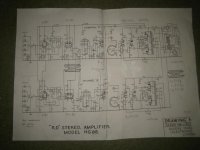
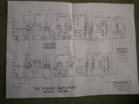
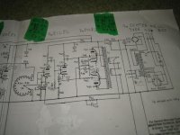
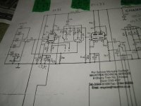
So, my question still stands, as I only have a schematic - hereby attached.
Dany, Toronto, Canada
Thank you for your valiant effort to solve my problem,
BUT the Mk1 comes w/ 2x ECL82's, 3x ECC83, 2x EF86, which's a totally a different kettle of fish.
For example Mk 2 has the ECL86's, etc. There're 2x R39'2(different R's - which're in my question!), There're different values for C32 & more of them into 2 cans. Same for the c24's. The chassis is different & so is the front panel. It also came to me w/ a mono FM tuner & 2 Wharfdale sp's.
So, my question still stands, as I only have a schematic - hereby attached.
Dany, Toronto, Canada
Attachments
Maybe 470r rather than 500? and then that would be in tolerance maybe?
You might end up having to make an educated guess at the second one, try one of that value, and see what the B+ ends up at. If you're lucky you might have voltages marked on the schematic at some points.
You might end up having to make an educated guess at the second one, try one of that value, and see what the B+ ends up at. If you're lucky you might have voltages marked on the schematic at some points.
A clear schematic is available here, but no parts list: https://www.audioservicemanuals.com/r/rogers/rogers-hg/6999946-rogers-hg-88-mk1-schematic
You will be referring to R53. The voltage on either side of it is shown in the schematic to which I have linked.
"the 2 filter power resistors (1 for each channel within the usual 2 lytics)"
You will be referring to R53. The voltage on either side of it is shown in the schematic to which I have linked.
Thank you for the help, but it looks that a lot of components are out of specs. Resistors I can read by their bands. Caps by their values, etc.
But now I came upon upon 2 values of identical caps in the same locations for each channel, which measure 1200 & 13000 Pf! Simply doesn't make sense. They're in the Filter CCT.
Dany, Toronto, Canada
But now I came upon upon 2 values of identical caps in the same locations for each channel, which measure 1200 & 13000 Pf! Simply doesn't make sense. They're in the Filter CCT.
Dany, Toronto, Canada
Hi
I deleted your question by mistake 2 days ago.
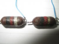
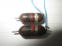
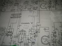
The coming from the Bass & Treble variable pots goes into the "Filter", then into the 2x C16 - The Questioned Values. These caps input the signal into the grids of V3a & V3b = ECC83. Their size is quite small = about 1cm long & 4 mm thick. I do notice a Red band @ 1 end - which will make it 1000 Pf - but they can't be so small in value. Perhaps their small physical size is because they're low voltage = no high voltage on 1 side & into the grid.
BTW, both grids of V3 have 2.2M to gound & 100K on the plate. 1 of the 2.2M & 1 of the 100K were out of specs. I found a close matching(to the other side of the ECC83 to eplace them.
D
Thank you, Dany, Toronto
I deleted your question by mistake 2 days ago.
The coming from the Bass & Treble variable pots goes into the "Filter", then into the 2x C16 - The Questioned Values. These caps input the signal into the grids of V3a & V3b = ECC83. Their size is quite small = about 1cm long & 4 mm thick. I do notice a Red band @ 1 end - which will make it 1000 Pf - but they can't be so small in value. Perhaps their small physical size is because they're low voltage = no high voltage on 1 side & into the grid.
BTW, both grids of V3 have 2.2M to gound & 100K on the plate. 1 of the 2.2M & 1 of the 100K were out of specs. I found a close matching(to the other side of the ECC83 to eplace them.
D
Thank you, Dany, Toronto
Hi. I agree w/ you that the caps can be .047 or perhaps .02 - but look @ the pics. The size of these caps are about 1cm = 2/8 length & 3mm = 1/8 dia, so how can such small dimensions contain .047? Besides look @ the bands = brn, blk, red. These mean to me 1,000 pf, considering the low signal @ these early tube stages. I also found some old amp tubes ccts I've & indeed they show what you're saying = .02, .047, even .1 Dany, TorontoI would expect coupling capacitor C16 to be in the order of 0.047 uF.
O.001 uF does seem low.
However, you said one of the caps measured 13000 pF (0.013 uF). Was that just a slip of your finger?
However, you said one of the caps measured 13000 pF (0.013 uF). Was that just a slip of your finger?
It must have been, or the mtr wasn't zeroed properly.
Here's a problem w/ 1 of them - the Sencore LC76 can't measure it. It does measure the other = very strange. Do you've an answer?
I also have an Elem\nco CM-1555 dedicated to measuring only caps. 1 measures 2330 Pf, while the other 4450 Pf. Thus, making the 1st close to the value rings = brn, blk, red.
The AM-91 Amprobe pro DMM, also measures properly - although slightly different than the Elenco.
Dany
Do you've an answer?
I'm afraid not.
I know just enough about valve amplifiers to have successfully renovated the Rogers HG88 Mk III, that I bought new in 1969.
Plus, I am chuffed that I managed to construct a simple ECL82 amp from scratch by interpreting an old magazine schematic!
Just to clarify, did your Rogers HG88 Mk I operate OK when those suspect capacitors were in circuit, and it is just a verification of the original value that you are after?
To Clarify:
This's not an Mk1 - it's just HG88 = ECL82's. The next versions, like yours, used ECL86's.
This HG88 has 2 500 ohm 3 watts for each section = Left & Right coming out from the Bridge rectifier = 1st thing. 1 of them was DOA.
There was hum - added some lytics(compact) in parallel & more.
Then, 1 of the o/p ECL82 cathode lytic was shorted - I changed many lytics & many out of specs resistors.
There was also a a Plate non making contact in the socket of the ECC83 before the 4x ECL82's.
The reason for all these replacements & mods is to obtain as much as possible equal Left & Right sections.
The 2 caps in question have their bands = color coded = Brn, Blk, Red = 1, 0, 2 = 2000 pf. So, 1 measures a bit more than 2000 pf, while the other shows I may be tempted to use 10000 pf's. &, I found 2 very close to each other.
I also have to shine the Brass clr front pannel - have 4 compounds to try the best.
I'll let you know when the amp is working properly.
Dany
This's not an Mk1 - it's just HG88 = ECL82's. The next versions, like yours, used ECL86's.
That's OK, Dany, I'm aware of the differences between the original HG88 and the succeeding two marks.
The clarification I was after was whether you had the amplifier working successfully at any point with those two 'dodgy' caps in place.
I now understand that you are trying not only to choose a suitable value, but also to make sure these capacitors match in both the left and right channels.
I'll be interested in learning the final outcome. 👍
Hi to all
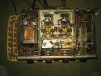
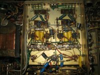
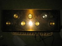
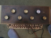
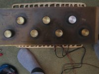
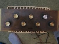
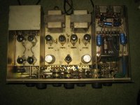
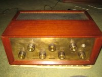
I finally fixed the HG88 & it sounds magnificent w/ 2 gold Tannoy 12" Dual Concentric in very large appropriate cabinets.
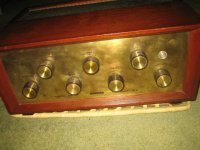
The sticking point - as I've discovered = very, very important - was precise resistors matching(1% or better) for the grids & plates of the pre ECC83 two sections(each side for the 2 channels) to the final ECL82's. Also removed the tarnish off the brass panel.
Thus, this amp is very finicky = very unusual. Of course I matched all the tubes on my AVO VCM3 - twice calibrated by me & w/ a new meter. The whole thing took a long time = well worth the results!
If anyone wants to see pics - I'' be glad to attach them.
Previously I've worked on my my Pilot 245-A. Next a Fisher X-100-A & a Heathkit AA-100 - requires lots of mods. Stay tuned!
Dany, Toronto
I finally fixed the HG88 & it sounds magnificent w/ 2 gold Tannoy 12" Dual Concentric in very large appropriate cabinets.
The sticking point - as I've discovered = very, very important - was precise resistors matching(1% or better) for the grids & plates of the pre ECC83 two sections(each side for the 2 channels) to the final ECL82's. Also removed the tarnish off the brass panel.
Thus, this amp is very finicky = very unusual. Of course I matched all the tubes on my AVO VCM3 - twice calibrated by me & w/ a new meter. The whole thing took a long time = well worth the results!
If anyone wants to see pics - I'' be glad to attach them.
Previously I've worked on my my Pilot 245-A. Next a Fisher X-100-A & a Heathkit AA-100 - requires lots of mods. Stay tuned!
Dany, Toronto
Thanks for the update, Dany.
I'm glad you've got this British antiquity working so well and would certainly appreciate some pics!
I'm glad you've got this British antiquity working so well and would certainly appreciate some pics!
Dany,
A Heathkit AA-100? Here's a link to a rebuild over on Audio Karma: https://www.audiokarma.org/forums/i...or-the-heathkit-aa-100-integrated-amp.204753/
I took a junker AA-100, liberated the trannies, yes I know, heresy to some, and rebuilt them into a poweramp/line level integrated. I didn't want to use the pentode triode driver/splitter stage so I adapted a Dynaco Doctor ST70 circuit. I incorporated the bias mods suggested by GordonW in the above linked Audio Karma article. The finished amp woks really, really well and drives a set of Spendors in our living room system.
Note: I used an IRL and a low value resistor in the PT primary to control the voltages due to the usual 120 volts plus the AC runs today.
If you decide to pass on the AA-100 project I'll take the trannies off your hands. 🙂
Steve
Hi Steve
I already have all the mods printed for the AA-100. I think these mods go deeper than the Audio Karma's. Have all the tubes already tested on my AVO VCM3. The finals are all OK so is the GZ. The others are also tested & if they need be - I'll replace them from my vast stock of tubes. In case the Gz is not OK & I don't have another 1 - I'll use a North American equivalent - obviously it has to be short. I think it's even possible to use a EZ81. Another possibility is to replace w/ Silicon diodes.
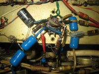
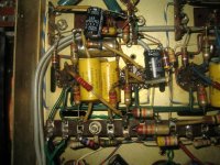
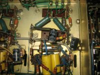
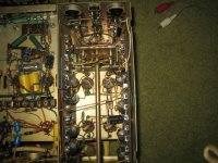
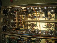
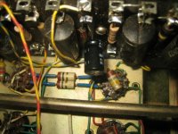
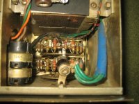
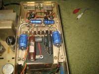
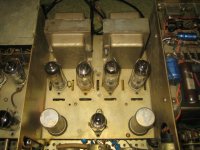
I'm attaching here a lot of pics of the finished HG88.
I already have all the mods printed for the AA-100. I think these mods go deeper than the Audio Karma's. Have all the tubes already tested on my AVO VCM3. The finals are all OK so is the GZ. The others are also tested & if they need be - I'll replace them from my vast stock of tubes. In case the Gz is not OK & I don't have another 1 - I'll use a North American equivalent - obviously it has to be short. I think it's even possible to use a EZ81. Another possibility is to replace w/ Silicon diodes.
I'm attaching here a lot of pics of the finished HG88.
Attachments
-
 IMG_0106.JPG63 KB · Views: 168
 -
 IMG_0107.JPG88.6 KB · Views: 131
 -
 IMG_0104.JPG27.8 KB · Views: 116
 -
 IMG_0105.JPG23.3 KB · Views: 113
 -
 IMG_0108.JPG74.2 KB · Views: 127
 -
 IMG_0109.JPG81.4 KB · Views: 121
 -
 IMG_0110.JPG81.2 KB · Views: 115
 -
 IMG_0111.JPG67.1 KB · Views: 174
 -
 IMG_0112.JPG70.1 KB · Views: 121
 -
 IMG_0113.JPG68.4 KB · Views: 164
 -
 IMG_0114.JPG36.5 KB · Views: 140
 -
 IMG_0115.JPG42 KB · Views: 108
 -
 IMG_0116.JPG45.8 KB · Views: 128
 -
 IMG_0117.JPG44.9 KB · Views: 128
 -
 IMG_0118.JPG62.4 KB · Views: 140
 -
 IMG_0119.JPG64.5 KB · Views: 129
 -
 IMG_0120.JPG58.8 KB · Views: 177
 -
 IMG_0121.JPG65.5 KB · Views: 361
 -
 IMG_0122.JPG58.6 KB · Views: 157
 -
 IMG_0128.JPG38.8 KB · Views: 161
- Home
- Amplifiers
- Tubes / Valves
- Rogers Developments UK HG88 Mk1