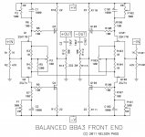
Does anyone know the direction the pots should be set to prior to powering on the balanced circuit?
Are P1 and P2 set full clock-wise or counter clock-wise? I'm finding it difficult to set the bias across R10 & 11 and zero out the output at R12.
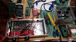
I'm monitoring with 6 multimeters and the numbers are all over the place. Also using a variac, but...
Since the circuit halves are joined together by R5, is it safe to assume that all 4 pots affect both halves when biasing and zeroing out the output?
Using dual +24v 0 -24v power supply capable of 1.5A, VRDN circuit. In other words, one dual supply for one channel or two circuits, and same for other channel.
Are P1 and P2 set full clock-wise or counter clock-wise? I'm finding it difficult to set the bias across R10 & 11 and zero out the output at R12.
I'm monitoring with 6 multimeters and the numbers are all over the place. Also using a variac, but...
Since the circuit halves are joined together by R5, is it safe to assume that all 4 pots affect both halves when biasing and zeroing out the output?
Using dual +24v 0 -24v power supply capable of 1.5A, VRDN circuit. In other words, one dual supply for one channel or two circuits, and same for other channel.
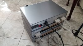
just measure for minimum resistance between JFet drains and adjacent rails (around 100R)
or between mosfet gates and adjacent rails (around 200R)
remembering trimpot rotation orientation is tricky and risky habit, worthwhile only if you have already printed ( or drawn by you) rotation arrows with clear explanation
or between mosfet gates and adjacent rails (around 200R)
remembering trimpot rotation orientation is tricky and risky habit, worthwhile only if you have already printed ( or drawn by you) rotation arrows with clear explanation

I just set up a BA3 preamp, not a BBA3. To set up my pots to 0V I had to turn them counterclockwise. I thought clockwise was the way to go but after applying the power it was apparent I was open instead of closed. Orientation may make a difference. Additionally, I only got 20V out of my VRDN and figured I'd tried it even though I was 4v short.
Works and sounds lovely. I'll work on my power supply and see if I can get the correct voltage. I'm interested to see if the sound improves or stays the same.
Works and sounds lovely. I'll work on my power supply and see if I can get the correct voltage. I'm interested to see if the sound improves or stays the same.
This is my 3rd BA3-pre...now need a balanced version. 🙂
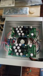
The VRDN as designed maxes out at 21v due to the de-noiser part of the circuit. It should work though, according to 6L6 in post above.
I removed the de-noiser parts and added a resistor to ground to makeup for the pot value.
Also, only used 10k uF per rail. It's solid at 24v. The VRDN minus "DN" has plenty of filtering, energy storage and a bit of transformer tuning up in front.
Have no doubt it will be just fine. 😉
Thanks
Vince
All pots, e.i. P1 and 2, are at minimum resistance at full counter-clock wise.
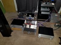
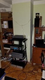
Got it working. Each half of the circuit for one channel needs reference to 0 volts, the midpoint between +24v and -24v on the power supply. I had omitted 0v on one half of the circuit. The symptom was erratic bias voltage and odd DC offset readings. This had happened to me before when the 0v connection disconnected from the power supply board edge connector.
It's dead silent with no music and attenuator fully opened. No sound at speakers at all.
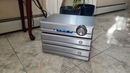
Shown driving F4s in mono balanced configuration. This is my 3rd version of the BA3-pre: low gain, switchable hi/lo gain and now balanced.
Thank you Mr Pass, 6L6 for the boards so many years ago now and to ZenMod for his omnipresence and always willingness to help.
Vince
Got it working. Each half of the circuit for one channel needs reference to 0 volts, the midpoint between +24v and -24v on the power supply. I had omitted 0v on one half of the circuit. The symptom was erratic bias voltage and odd DC offset readings. This had happened to me before when the 0v connection disconnected from the power supply board edge connector.
It's dead silent with no music and attenuator fully opened. No sound at speakers at all.
Shown driving F4s in mono balanced configuration. This is my 3rd version of the BA3-pre: low gain, switchable hi/lo gain and now balanced.
Thank you Mr Pass, 6L6 for the boards so many years ago now and to ZenMod for his omnipresence and always willingness to help.
Vince
Attachments
Question about balanced vs unbalanced negative pin grounding.
When running output in unbalanced mode, does the negative XLR pin need to be grounded?
Currently running unbalanced without negative pin grounded and not experiencing any abnormalities.
Like to know if I'm missing something or why this works. thanks.
Comparing it against the (new to me) XP30! 😉😉
When running output in unbalanced mode, does the negative XLR pin need to be grounded?
Currently running unbalanced without negative pin grounded and not experiencing any abnormalities.
Like to know if I'm missing something or why this works. thanks.
Comparing it against the (new to me) XP30! 😉😉
Wow. Congratulations Vince!  Have you tried the XP30 in the high gain mode yet? Plenty of gain for the F4. 🙂
Have you tried the XP30 in the high gain mode yet? Plenty of gain for the F4. 🙂Hi Dennis, due to limited space at the moment I'm using a 3W Class A power follower based on a circuit in the the F5 article. Also 500w Class-d IcePower mono-blocks. Can you guess which is more engaging? 😉 Haven't needed to change to the high gain setting. On 82 out of 100 on the volume pot. Plenty of output. I couldn't pass up a deal from Reno HiFi, thanks to Mark Summut for making this possible!
Listening to some Rush while working...go Canada! 😀
Listening to some Rush while working...go Canada! 😀
I'm glad for ya!!
I know we are all biased, heavily ........ Papamp is not just an amp, for us Greedy Boyz

Thanks ZM. It's a little bit of a dream come true to own a factory made Pass product. Only took me 29 year since Zen amp article in AA! Was a fan before the 1994 article. As you know, it can power an output stage directly and bi-amp as well. Not impossible to DIY, I know, but look at that chassis! Come on! 😀 😀 😀
Maybe you can answer off the top of your head-
Question about balanced vs unbalanced negative pin grounding.
When running output in unbalanced mode, does the negative XLR pin need to be grounded?
Currently running unbalanced without negative pin grounded and not experiencing any abnormalities.
Like to know if I'm missing something or why this works. thanks.
Thanks,
Vince
My Memory of Not Remembering is absolutely functional, ,so I don't remember ........... 
Anyway, I believe that Aleph P, or it was BoSoZ - it was declared that thingie works better when both outputs were equally loaded so, in case of using just one output, second one needed to be terminated with resistor of same value as connected SE amp Rin
Now, knowing your preamp circuitry just by principle, I'm sure that established symmetry of operation is totally in-dependable of Rload, so I'm 99% sure that you can leave unused output phase floating ....... and there is even misty idea that I heard it's having separately buffered RCA out .....
In any case, ZM as ZM, declaring things close to 158% of certainty .......... but to be frank, last 1% of uncertainty only our Wayne is able to cover
it's easy to check - two ways:
- listen with neg phase floating, then listen with neg phase loaded with resistor of amp Rin value
-check with ohmmeter - are XLR pin 2 and RCA hot shorted?
-mail PL/Wayne
that's 3, but I'm perfect with Math
Hi Vince,
I leave XLR output pin 3 floating on mine when using SE; only short XLR input pin3 to G. You could try doing what ZM says which is to connect XLR output pin3 to G thru a 48Kr resistor(typical Pass power amp input impedance). I have tried it and cant detect any difference.
Fun starts when you start adjusting P3 and want that elusive negative H2.
nash
- Home
- Amplifiers
- Pass Labs
- BBA3 as Preamp Question