Hello everyone,
I am attempting to repair an old car audio amp. it is an Earthquake T2000W/4
and I managed to find the schematic: https://drive.google.com/file/d/1zqfWyQ9OT4StDlfMfhDePenB9qFjxkkN/view?usp=sharing
When I received the amplifier it was in very bad condition, left out to the elements.
I cleaned the board and replaced all the power supply FETs as they were blown/missing.
Also substituted in a rectifying diode pair from another amp which was missing.
replaced the blown blade fuses. and checked all the output BJT's. the BJT's all seem to be ok and unharmed.
The problem is I power up the amp and when I try play music it is extremely distorted and scratchy. ( On all 4 Channels )
Also the protect light is permanently on.
I tried removing all 8 BJT's and the protect light is still permanently on.
I scoped the power supply and the output is 50V DC and looks clean.
I'm not sure why the protect light is on and why the audio is so terribly scratchy and crunchy.
Please let me know if you have any suggestions.
This is my first post here and I'm quite new to the scene so please excuse any informalities.
Regards,
Alex
Last edited:
Hi ! You checked the bias voltage of the output transistors?also check before mounting the final transistors by inserting a 1khz signal with the oscilloscope check that the sinusoid that enters the base of the output transistors is a precise sinusoid
Hello Paolocognigni!Hi ! You checked the bias voltage of the output transistors?also check before mounting the final transistors by inserting a 1khz signal with the oscilloscope check that the sinusoid that enters the base of the output transistors is a precise sinusoid
Thanks for your reply.
Please excuse my ignorance but how do I check the bias voltage?
I will check the 1KHz test on where the base of the BJT would go.
for the bias voltage check between the emitter and the base of the output transistors, you should have about 0.7V or 1v maximum and by inserting a signal at the input of the amplifier you should see with the oscilloscope on the base of the output transistors a signal clean
Thanks!
With the BJT's removed I get 250mv between Base and Emitter pads on the board.
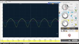
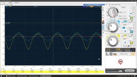
Attached is my scope results of 1KHz test tone, Blue is input, Yellow is Emitter pad on first pic, Base pad on second pic.
If I adjust the gain higher the signal starts clipping on one side only and distorts even more!
What could be causing this?
With the BJT's removed I get 250mv between Base and Emitter pads on the board.
Attached is my scope results of 1KHz test tone, Blue is input, Yellow is Emitter pad on first pic, Base pad on second pic.
If I adjust the gain higher the signal starts clipping on one side only and distorts even more!
What could be causing this?
Attachments
check the previous stage maybe the problem is on the bias transistors! I had a similar problem on an amplifier and I solved it by replacing the transistors
This is observed on both the NPN and PNP BJT pads for each channel. On all channels. Only difference is signal is inverted on channel 2 and 4 presumably so outputs can be bridged.
Ok thanks I will check the transistors before the output stage when I get home. 🙂 Hopefully I can figure it outcheck the previous stage maybe the problem is on the bias transistors! I had a similar problem on an amplifier and I solved it by replacing the transistors
I am trying to find out where the signal is being corrupted by probing around.
I see output of the op-amps NJM4558L have a beautiful clean boosted signal of about 5V.
Just after this the signal goes through R330 where on the other side the signal is very small, looks like it's being pulled to ground.
So I see on the other side of this resistor there is a transistor Q313 S9013 which is between ground and base is connected to something called VT ?
Can anyone explain what VT is ?
On their other side of the schematic I see it's involved with the TL494CN PWM controller and the Protect LED is in there too.
So I'm just suspicious of this VT line because I notice the protect LED is stuck on. Maybe this is something to try disable the input signal when protect light is on?
Yes my suspicion seems correct! 😀 I removed the S9013 transistors and now the signal on the output stage BJT is a perfect sine wave!!! The bias measure between base and emitter on output BJT pads is between 0 and 1V depending on the gain while playing the sine wave. Hope this is correct ?
Does anyone know what this VT line is ? If I fix the issue triggering protect light and VT maybe the amplifier will be repaired?
This feels like such an accomplishment I'm going to sleep well tonight.
Does anyone know what this VT line is ? If I fix the issue triggering protect light and VT maybe the amplifier will be repaired?
This feels like such an accomplishment I'm going to sleep well tonight.
Last edited:
Amplifier repaired! Replaced Q20 and Q22 on the schematic with generic 2N3904s I had lying around and deadbugged 10KOhm base resistors 😀 works great now.
Seems like when the power supply went blam it damaged the protection circuitry. The failed transistors were holding the amp in protect and attempting to disable the Input signal using that VT line.
Thanks for the help @paolocognigni I appreciate it. So chuffed I was able to repair this amp that looked like it was nuked then left in the Forrest for a year. Seriously it has like mud and dirt inside and so much rust. I scrubbed it clean in the sink with dishwashing liquid and dried it in the blazing sun for a few hours. xD
Great good! I'm glad I was of help to you! I think Vt is probably the muting system I have seen on other types of amplifiers !!
😉
😉
- Home
- Amplifiers
- Solid State
- 4CH Class A/B repair help [Earthquake T2000W/4]