Anyone have circuit diagram to share or sell to build for the Hammond 1650w tranfomer power amplifier thanks
At 28 pounds each that a lot of transformer. Do you already have the 1650Ws? Do you really need 150 WPC? Not trying to discourage you, just curious.
S.
S.
People tried to “discourage” me too but I did it anyway. Like bass? You could power a small disco with these. Seriously — they blew away my first Phase Linear, which was actually used for mobile disco. 300 watts “music power”, calculated from peak o-scope readings, 210 watts continuous sine wave.
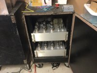
Yeah, the rack is heavy. So is the one loaded with CA18’s and so are the lab horns. I’m used to “heavy”.
Yeah, the rack is heavy. So is the one loaded with CA18’s and so are the lab horns. I’m used to “heavy”.
Attachments
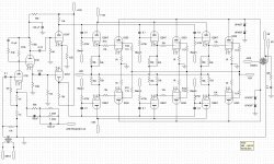

That is a very serious amp. I like the cathode follower drivers of the output tubes with solid state power supply. Fantastic driver (so maybe one driving multiple 6550s?) and it keeps the 6550 grids negative until the cathode followers have warmed up. Why not 6SN7s as a cathode follower? Maybe the warm up time is too short? I personally like Maida (Millett version) regulators. I think they have better performance than the zeners.
6550’s are particularly picky about g1 resistance, which is why the direct drive followers in the first place. Rk of just about any little triode is at most a few hundred ohms, so it could drive multiple 6550’s. But then you lose the ability to individually bias them. Depending on matching, an overall balance control may be enough. I suppose you could use 6SN7’s, but I wanted to use something that can take being run a little hotter while still being available new. And didn’t want to use up all of my old stock 6SN7 Sovteks some place where linearity didn’t matter as much. If I didn’t intentionally limit this project to standard audio tube types that are in production, I might have gone with 6BL7s for drivers.
Warm up and stabilization time is done the brute force way. I have a 555 timer and relay set to turn on the HT and 6550 heater power trafos 15 seconds after throwing the power switch. Whole front end comes up first. The 4 transformer power supply was me being a cheapskate and wanting off the shelf units. A custom made unit would have been well over $200 per channel the Anteks cost, probably more like $500. And at the time I didn’t have suitable cores or all the wire on hand to wind my own. Separate trafos works out better for the delayed start anyway.
Warm up and stabilization time is done the brute force way. I have a 555 timer and relay set to turn on the HT and 6550 heater power trafos 15 seconds after throwing the power switch. Whole front end comes up first. The 4 transformer power supply was me being a cheapskate and wanting off the shelf units. A custom made unit would have been well over $200 per channel the Anteks cost, probably more like $500. And at the time I didn’t have suitable cores or all the wire on hand to wind my own. Separate trafos works out better for the delayed start anyway.
wg_ski,
You can have DC coupled drivers to single or parallel output tube g1 grids.
At the same time you can have individually biased multiple output tubes, such as in a parallel push pull circuit.
But you have to use Individual self bias cathode resistors and Individual cathode bypass caps (or multiple CCS constant current sinks and multiple bypass caps).
Sorry, I know self bias is viewed negatively by some designers.
All bias circuits have one or more tradeoffs.
For any engineering problem, there are at least 100 'solutions', and at least 3 of those solutions will work . . .
but only if they are implemented properly.
YMMV - Your Mileage May Vary
And, although 6550s are picky about the maximum return resistance for g1, self bias has a higher maximum return resistance rating than the maximum g1 return resistance when using fixed adjustable bias.
But KT88s are mostly similarly specified, but with the advantage of higher maximum g1 return resistance rating than the 6550.
All tubes vary from their ratings. Some exceed, some are worse than their specs.
The only experience U have with delayed supplies are for such things as 1kW, 10kW, and 45kW transmitters, Sonars, etc.
Hi Fi and Stereo playback tube amplifiers . . . I have no experience with delayed supplies other than indirectly heated rectifiers (intrinsic B+ delay); and series resistors to drop excess voltage from the filament secondaries to the filament. With filaments that often have cold resistance of 1/4 the hot resistance, the series resistor provides intrinsic soft start delayed full filament voltage.
Last edited:
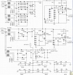
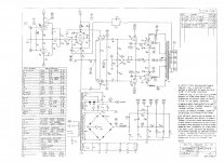
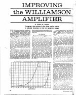
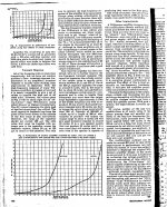
We build amps that are very similar to wg_ski , but Maida regulated screens and modified Williamson driver ( see "Improving the Williamson Amplifier by Talbot M. Wright) with additional cathode followers (the driver stage regulated from the single Maida regulator). This allows optimal g1 resistors. We have found that we can reduce the bias current on the tubes to AB2. We don't individually bias the tubes. There are no problems running up to eight tubes this way, with only individual bias for the top four and bottom four. Reducing bias current increases stability and tube longevity.
Attachments
-
Williamson- Improving the p01.GIF5.1 KB · Views: 89
-
Williamson- Improving the p02.GIF5.7 KB · Views: 57
-
Williamson- Improving the p03.GIF5.7 KB · Views: 48
-
 Williamson- Improving the p01.jpg697.2 KB · Views: 86
 -
 Williamson- Improving the p02.jpg774.1 KB · Views: 103
 -
 Williamson- Improving the p03.jpg983.2 KB · Views: 96
When there is that much feedback, you can reduce the bias quite a bit. I’m only running 20 mA per 6550. It actually gets quite listenable once you get it above 3mA and almost acceptable at 8. It surprised me just how little I could get away with.
Kind of an old habit to break - I’m used to building kW solid state PA amps and only running a couple of mV on the emitter resistors instead of the usual 20-30.
Kind of an old habit to break - I’m used to building kW solid state PA amps and only running a couple of mV on the emitter resistors instead of the usual 20-30.
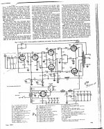
wg_ski thanks for posting the schematic. What is the reason for the choice of a high mu triode for the first stage and concertina? What is the purpose of the 4007 diodes from the 6550 plates to ground? Thanks.
More open loop gain than another SN7. Some use a little pentode for even more, but then you have to move the dominant pole down. Higher mu is less desirable as a concertina, but with that X14 gain stage after you only need two or three volts out of it.
The 4007’s are for overvoltage protection. You can run it without a load without frying the OPT. It’s been tested, for about 2 hours with music run up to heavy clipping (load disconnected). The output zobel alone might be enough, but I didn’t trust it with a $350 OPT. Those diodes always work for SMPS’s, although you want fast ones for that.
The 4007’s are for overvoltage protection. You can run it without a load without frying the OPT. It’s been tested, for about 2 hours with music run up to heavy clipping (load disconnected). The output zobel alone might be enough, but I didn’t trust it with a $350 OPT. Those diodes always work for SMPS’s, although you want fast ones for that.
- Home
- Amplifiers
- Tubes / Valves
- Hammond 1650w hifi circuit diagram