I broke a rectifier going through the trouble shooting procedure from the service manual.
I am having difficulty finding a replacement; specs appear to call for a silicon rectifier, 200mA, 200PRV & 250mW.
Another question is, should the discoloration on the back of the circuit board be telling me something?
Looks like old solder flux to me. Shouldn't affect the circuit performance. Can be removed with alcohol and a tooth brush. It's always a good idea to inspect the soldering on older equipment, looking for cracked or thermally stressed joints, especially on parts that may get hot like power resistors and semiconductors. Re-solder anything that looks questionable.should the discoloration on the back of the circuit board be telling me something?
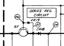
The diodes appear to be HP Mfr parts, no longer available... Basically it is just a signal diode clamp used for protection of reverse voltage & overvoltage clamping.In the service manual, is there not a parts list? And does it call out a specific part number?
Hopefully the Q7 diode is not toast (which protects Q7 from zener-ing the Base-Emitter junction).
Attachments
Thank you all for your input.
I thought it was probably just flux techtool but am not experienced enough to be certain. Thanks for confirming.
Now that vinnysj showed me Mouser does have the replacement part, I can order some and continue with the problem solving procedure.
Should this unit have the caps replaced like old stereos? (Since I have to pay shipping on the diodes, might as well try to preplan to get what is needed.
I'll order plenty of those diodes but I wondered if you would replace the diodes around Q7 automatically? At this point I was just going to replace CR4 and continue the trouble shooing procedure.The diodes appear to be HP Mfr parts, no longer available... Basically it is just a signal diode clamp used for protection of reverse voltage & overvoltage clamping.
Hopefully the Q7 diode is not toast (which protects Q7 from zener-ing the Base-Emitter junction).
View attachment 1026505
Should this unit have the caps replaced like old stereos?
Unless they measure open or very high ESR, I wouldn't. These units are quite robust.
Thanks jbau. Glad to hear the robust confidence, I hope this unit will serve me well after spending some time and money on it.
It sure looks serious. 🙂
It sure looks serious. 🙂
They're nice supplies. Just make sure to keep some space on the top and bottom for air to enter/exit for cooling. I'm sure the manual gives the minimum spacing required.
It just occurred to me that posting the problem may lead to a quicker solution than the manual trouble shooting steps.
When the unit is powered on, the voltage meter needle pegs.

When the unit is powered on, the voltage meter needle pegs.
It's acting like the sensing is not connected. A couple things to check before looking at the circuit. Verify the connections on the terminal block on the rear are as per the manual for front-panel output. It also could just be an oxidized meter select switch. Squirt some IPA into it and work it around.
Thanks for the tips jbau!
I hit the selector knob with Deoxit..
Thanks, I should have thought of that one since I knew old stereos often had the problem.
Strapping is as illustrated. Is the resistor showing where a load MAY be connected?
There is nothing where the resistor is shown. I'm afraid I am missing how front panel output is set otherwise?
Last edited:
Thanks for the tips jbau!
I hit the selector knob with Deoxit..
Thanks, I should have thought of that one since I knew old stereos often had the problem.
Strapping is as illustrated. Is the resistor showing where a load MAY be connected?
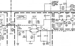
Yes, RsubL in the pic represents the load. Industrial users would typically rack-mount these things and permanently connect the load at the rear terminals, as shown.
I assume you want to use the front panel output terminals. Just in case it isn't obvious... this thing develops power between the + and - terminals. Either side can be grounded. Notice in that pic that the + term is strapped to ground, making that channel a -V output. For a +V output, strap ground to the - term. Or if you want to be able to set the output polarity of each channel at the front panel terminals, lift the ground strap and connect it as desired at the front panel. Or use it floating.
Does "- Out" under Meter Common in the 5-3 table below mean "-S" on the schematic?
Seems like it must not since it says +S elsewhere but I don't see it.

Seems like it must not since it says +S elsewhere but I don't see it.
The +S and -S terminals are for remote sensing. Used when the load is not near the power supply and there may be voltage drop in the wires between. Another set of wires is connected from the load back to the S terminals so the supply can measure the actual load voltage and regulate accordingly. Again, not normally used if the supply is used on the test bench, so they are tied to the outputs.
And if you haven't already, clean and tighten all the jumper connections on the terminals. Any resistance between the output and S terminals will force the output voltage up.
I may have missed it earlier, but: Program notes--- a link to the service manual:
https://www.keysight.com/us/en/assets/9018-05509/user-manuals/9018-05509.pdf?success=true
https://www.keysight.com/us/en/assets/9018-05509/user-manuals/9018-05509.pdf?success=true
That is a more clear copy of the manual BSST. Thanks
I wouldn't have considered cleaning the jumpers; will do techtool.
Testing Results:
0 volts on pin 31 to +S -should be 6.2V
31 volts on pin 41 to pin 38 -should be 3V
41 volts on -OUT to pin 27 -should be 0.4V
I wouldn't have considered cleaning the jumpers; will do techtool.
Testing Results:
0 volts on pin 31 to +S -should be 6.2V
31 volts on pin 41 to pin 38 -should be 3V
41 volts on -OUT to pin 27 -should be 0.4V
- Home
- Design & Build
- Equipment & Tools
- HP6253A Power Supply Help