The factory preamp design in the Onkyo A-5 is marginally stable. This thread is about a complete and tested fix which retains the TA7136P IC, preserves in-band behavior, and doesn't involve any drilling.
I live a half-mile from a strong FM radio transmitter. This is a good way to find out which preamps are stable: that FM broadcast bleeds right through the noise floor for those that aren't.
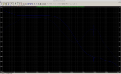
The A-5 preamp showed the usual signs of oscillation. It had an angry noise floor that varied in volume if you touched the chassis or moved any attached wires. You didn't need a source if you wanted to listen to one particular FM station. The FM pickup was worse with the chassis off, and audible with it on. A stable preamp shouldn't become a tuner even with the chassis open.
The fix is in 3 parts, there will be a post for each.
I live a half-mile from a strong FM radio transmitter. This is a good way to find out which preamps are stable: that FM broadcast bleeds right through the noise floor for those that aren't.
The A-5 preamp showed the usual signs of oscillation. It had an angry noise floor that varied in volume if you touched the chassis or moved any attached wires. You didn't need a source if you wanted to listen to one particular FM station. The FM pickup was worse with the chassis off, and audible with it on. A stable preamp shouldn't become a tuner even with the chassis open.
The fix is in 3 parts, there will be a post for each.
- Create a spice model of the TA7136P op amp so we can evaluate its stability.
- Change the compensation so that the circuit is stable in spice.
- When that doesn't work, notice that the NFB loop is physically large (it spans 3 circuit boards). Reduce NFB node impedance at HF, to improve the chance that our spice model is accurate. This worked.
Last edited:
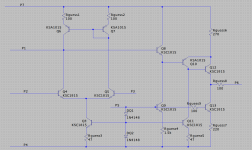
The TA7136P datasheet includes an equivalent circuit. Unfortunately it omits all the resistor values though, so we have to make some guesses.
Resistor "Rguess6" seems to be important, its value has a large effect on the stability plots. It's possible to indirectly measure Rguess6 by drawing current from the output pin and checking the voltage drop at compensation pin 3. Doing this on a real TA7136P yielded a value somewhere in the range of 270 to 300 ohms for Rguess6.
The other guesses put the overall current draw about where it should be, and they put the pin 3 voltage about where it is on a real part -- and ensures that the current mirror isn't saturated.
This should be close enough to do some analysis, if the claimed "equivalent circuit" really is.
Attachments
Simulating the factory circuit reveals that phase margin is pretty bad -- about 20 degrees.
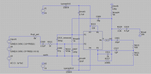
Here's a first attempt to change the compensation to get this stable. While this looks great in spice, the actual circuit still picked up FM :-C
The trouble is likely that the Baxandall network (abbreviated here as R415 and R421) is several inches away and spread over two PCBs connected by a lengthy wiring harness. It's probably contributing some parasitics that I don't know how to model in spice.
Attachments
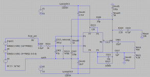
The lengthy NFB loop and Baxandall circuit behaves like who-knows-what at HF.
We can add cap Cmod3 to form a capacitive divider with existing C311, creating a new NFB loop at HF where the impedance of these caps falls below that of the Baxandall network and so this new NFB loop will dominate. The reduction in HF impedance and the physical proximity should bring the actual circuit into closer alignment with the behavior that spice predicts; knock on wood.
It seemed to work -- this circuit gets rid of the radio pickup. The noise floor is lower; it sounds passive, like thermal noise hiss; and it no longer "jumps" with a hand on the chassis.
All the mods were:
- Remove C313. This boosts in-band loop gain from ~40dB to ~60dB.
- Replace C307 with 120pF in series with 1k.
- Replace C309 with 39pF.
- Replace C311 with 12pF -- probably the original 8pF value would work fine too.
- Add Cmod3 (120pF) to form the capacitive divider mentioned above.
- Add Cmod5 (120pF) and Rmod4 (56). This creates a low impedance load for the preamp at HF. Maybe not necessary but it adds to the margins.
- Add decoupling caps Cmod1 and Cmod2. This probably wasn't needed; the supply isn't that far away. But it's easy to do, the factory left unpopulated pads for them.
- R311 reduced from 4.7k to 1k. Optional. Reducing the input impedance improves distortion performance a bit, though we're in series with the volume pot here so there's only so much you can do.
Attachments
The TA7136P isn't bad: you get a current mirror, buffered VAS, and external compensation flexibility. Single channel means "dual mono" -- you just need two 🙂
The finished preamp simulates around -100dB distortion floor at worst-case volume setting and signal level. Not bad for a 45-year old op amp. In the right application it can work well.
The finished preamp simulates around -100dB distortion floor at worst-case volume setting and signal level. Not bad for a 45-year old op amp. In the right application it can work well.
The bigger siblings to the Onkyo A-5 were the A-7 and A-10. These use a different preamp circuit. It's a simple 3-transistor arrangement: a balanced pair with resistive load and a single VAS transistor. They might have the same issue -- the Baxandall loop is again spread over 3 PCBs and returns directly to the negative input which could invite RF pickup. They might need a similar fix.
Three transistors isn't enough for an accurate preamp. You're better off with the TA7136P in the A-5... well maybe not the way the factory sent it, but with the fix 🙂
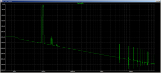
Here's simulated distortion performance on the A-5 with mods, assuming an 8k source impedance from the volume pot. Better than -110dB -- excellent.
Three transistors isn't enough for an accurate preamp. You're better off with the TA7136P in the A-5... well maybe not the way the factory sent it, but with the fix 🙂
Here's simulated distortion performance on the A-5 with mods, assuming an 8k source impedance from the volume pot. Better than -110dB -- excellent.
Attachments
ps. This follow-up post analyzes the performance of the TA7136 in its own datasheet's reference circuits.
Surprise: the datasheet's reference tone control circuit is unstable. No wonder so many TA7136 applications behave badly.
Toshiba could have taken the NE5532's market with this chip, and done so years earlier, if the application notes had been half decent and the part was easy to implement in low-distortion circuits that behaved well. That might have saved the externally-compensated opamp, whereas bad reference circuits may have doomed it.

- Home
- Source & Line
- Analog Line Level
- Stabilizing the TA7136P-based preamp in an Onkyo A-5