Hi All (First Thread). I am not very fluent with electronics but I am hoping for some guidance troubleshooting my amplifier. It was working before I opened it up to replace an RCA input jack. I did that and blew out considerable dust with compressed air. Now it stays in protection mode. I have a multimeter and downloaded the PDF for the amp. Where should I start?
Check for cold solders. You may have damaged some pre-cracked solder joints while blowing out the unit and/or touching something during that.
That might be be "best case".
That might be be "best case".
Oh dear...
First check I would do (assuming the amp powers up safely with no smoke etc) would be to see if there was excess DC offset at each channel output (measure before the relay), and then check the supply rails.
Maybe you have blobbed some solder accidently and shorted something out or perhaps some solder has fallen from the iron on to the PCB.
I'll try these checks. Thanks. If I can ask some novice questions... How do I know if I am measuring before the relay? I would have thought to just measure where I connect the speaker wire, but that must be after any relay? How do I identify supply rails? Will I be able to identify cold solder joints by just looking? Should I pull the circuit boards out to inspect?
Try and disturb it all as little possible initially. The supply rails are all the voltages produced by the power supply to supply the various parts of the amplifier.
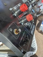
DC offset can be measured here (arrowed) and the - and + 72 volt rails are just two of several but these feed the main output stage. Check the offset first. It should zero volts DC.
( be very careful not to short anything when measuring voltages)

DC offset can be measured here (arrowed) and the - and + 72 volt rails are just two of several but these feed the main output stage. Check the offset first. It should zero volts DC.
( be very careful not to short anything when measuring voltages)
Its difficult working from photos tbh. You need your black meter lead on ground and just measure with the red lead to any of those resistors or coils (L801, L803 or R801, R803). All will show the same voltage whatever that might be.
All you are doing is measuring the voltage on that line between connectors '29' and '31' and those components looked the easiest way to get easy access.
So 9 volts shows a problem if you are measuring correctly.
If both channels have the same sort of offset then that shows a common issue which could be power supply related.
The amp has a lot of fuses but if any are blown you have to ask why that happened seeing as it all worked before.
The amplifier has multiple supplies and some like the transistor regulated supplies are duplicated between channels.
I would urge you to backtrack on all the work you did and look visually for any problems because ultimately this is something that has occured with you working on it. Whether that has caused actual damage to anything remains to be seen.
Thanks very much for the help! Okay, it sounds like that's what I did to get the DC offset voltage. If I understand correctly, that will be how I measure all of the voltages (with black probe grounded and red probe on the point being measured?)
Fuses. I checked them all (for "continuity:" voltmeter beeped to confirm they hadn't blown), but I did not remove them for that test. Should I have?
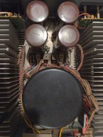
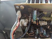
A Thought. As I remember replacing the RCA jack, I did also temporarily remove the speaker units screws while cleaning up some plastic covers on the outside of the chassis. It is very likely that in doing so, some of the solder connections on the speaker unit circuit board touched the heatsinks. I really doubt that I would have had the AMP plugged in or turned on while I did this, but I can't entirely rule out that possibility. Thought I would mention it.
Fuses. I checked them all (for "continuity:" voltmeter beeped to confirm they hadn't blown), but I did not remove them for that test. Should I have?
A Thought. As I remember replacing the RCA jack, I did also temporarily remove the speaker units screws while cleaning up some plastic covers on the outside of the chassis. It is very likely that in doing so, some of the solder connections on the speaker unit circuit board touched the heatsinks. I really doubt that I would have had the AMP plugged in or turned on while I did this, but I can't entirely rule out that possibility. Thought I would mention it.
Fuse are checked either with the amp OFF (and with the meter on a low ohms range) and you should find they read 'short circuit'. In other words a reading that is the same as when you just short the probes together. The meter must be on a low ohms range, that is to say a range that resolves resistance values down to 1 ohm or lower.
A 'beep test' alone isn't sufficient because the meter may interpret the very large capacitor values in the power supply as a short and just beep.
Another way to test is to measure the voltage on each end of the fuse with the amp ON while setting the meter to an appropriate voltage range (and selecting AC or DC as appropriate to the circuit). You should see the same voltage at each end of the fuse.
A third way is to check voltage across the fuse with the amp on. There should be no voltage across a good fuse.
Most voltage checks are from ground to the point being measured (but not always... example being the fuse checking and looking for voltage across the fuse).
If you think the amp might have actually been on 😱 then all bets are off. It would be so easy to cause damage in that state. Always always have the amp unplugged from ALL external connections and not just the mains before working on it and touching a soldering iron anywhere.
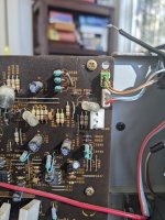
Alright Mooly. I checked the fuses using method 1 above. All are good. I attached the circuit board diagrams here instead of the schematic so you would know exactly where I put the probe when I took the measurements. Does this make sense?
Attachments
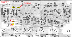
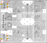
First image looks OK with correct plus and minus 70 volts. You have 'no' voltage on the fuses because you need your meter on AC volts for that. They must be OK or the 7 volts would be missing.
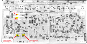
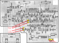
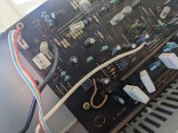
Second image. The devil is in the detail and I assume TR704 voltages are negative 70.
Third image looks OK.
Fourth image looks OK.
So all the main supplies look good and yet you have that 9 volt DC offset which I think was on both channels? That's really important because it suggests something common to both channels.
I'm struggling to see anything that fits in with that tbh. One channel yes but not both.
Another idea given that nothing went back or smoked. Is it possible something has gone amiss with the socket you replaced such as missing ground or disconnected plug somewhere? I'm just thinking that maybe the fault isn't so much a DC offset as perhaps an unwanted AC signal of some sort, perhaps low level oscillation that could be asymmetric and so appears as a DC offset.
Most DC offset faults would just bang up hard against a rail and so 9 volts is a bit of a non standard fault scenario.
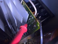
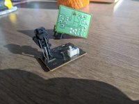
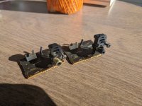
Thanks again for the help. Here is some more info about the rca Jack's. The original ones have three wires. Two of the wires go to ground (?) On the jack (the outside contact), but they go to different locations on the amp. One attaches to a bare wire called JV73. The other ground goes to CN3B. My generic replacement jack has just the ground and pin/center. I connected both black wires from the amp to the ground on my replacement jack.
Some notes:
- pictures show missing outside contact on one side. That's why I replaced it.
- While trouble shooting, the wire has pulled off from JV73.
-All my measurements have been with JV73 not connected on one side and CN3B disconnected on both sides.
-I will reattach that JV73 wire and plug the CN3B connectors back in and see if anything changes.
Attachments
-
 PXL_20220219_142319042.jpg313.5 KB · Views: 220
 -
 PXL_20220219_143042355.MP.jpg437.8 KB · Views: 128
 -
 PXL_20220219_143002310.MP.jpg516.4 KB · Views: 133
 -
 PXL_20220219_143149984.MP.jpg184.4 KB · Views: 131
 -
 PXL_20220219_143058129.jpg360 KB · Views: 151
 -
 PXL_20220219_143858739.MP.jpg494.3 KB · Views: 143
 -
 PXL_20220219_144607118.jpg392.6 KB · Views: 146
Okay. With jacks reconnected measurements are the same. I did change to AC at those points and I see AC voltage as you said.
Really appreciate the guidance.
Really appreciate the guidance.
It is really difficult working off pictures 🙂 Look at point CN3A on the main amplifier part of the circuit.
1/ With the new sockets all connected up do you have continuity (use a low ohms range on your meter) between pin 2 and pin 3?
2/ Points 2 and 3 should also read zero ohms (so continuity) to the main ground point in the amplifier. What the route for that might be is unclear. Look at the diagram and the earth symbol on the left. That point should electrically return to the same point as the speaker negative terminal.
So have you got continuity from points 2 and 3 of CN3A to the speaker negative terminal?
Amp OFF of course for all these checks.
I get 36kohm across pin 1&3.
There is no wire in the plug at Pin 2, but I get infinite ohms between 2 and 3. I get zero between JV73 and point 3. (I have the US/Canada model). Same on both channels.
When I ground one probe on heat sink on right channel:
Point 1: 113kohm
Point 3: 77kohm
JV73: 77kohm
Right Speaker Negative
Point 1: 5.77Mohm
Point 3: 1.272Mohm
JV73: 5.7Mohm
Left channel:
Point 1: 36kohm
Point 3: 0.3ohm
JV73: 0.3ohm
Left Speaker Negative
Point 1: 1.328Mohm
Point 3: 5.7Mohm
JV73: 1.258Mohm
My multi meter decides when to us k or M. I just recorded what I saw.
The standout thing there is the left channel reading 0.3 ohms from point 3 and the wire to ground. That all sounds correct. So the right channel is missing the ground continuity and I can't really advise why that is so without having it in front of me.
In the first instance you will have to just compare channels visually and see where the left channel gets that ground connection from. It could be via that wire.
(Most auto ranging meters should have a facility to manually select and then hold a given range but it sounds like yours is at least resolving things OK)
I sold modules from its older brother to a nice guy who Oster told med which components were bad om mine and the one it turned donor for. I Will try to find the conversion and translate, allthough I know next to nothing about how amps work. I installed L25D modules instead since they thrive on 70 volts. Good luck. Seems like you are in good hands
Cheers!
Cheers!
Not sure of your issue, but I have a PMA-2000 and the protection would not switch on the amplifier sometimes. I would move the amplifier around and it would work, then not work the next time. Obviously, a loose connection. I ended up accessing the protection board that's under the transformer you access from the bottom and there was a ribbon cable soldered directly to the board. I resoldered the ribbon cable connections and issue went away. If you jar around this amplifier the ribbon cable can be flexed and it ends up causing cold solder joints where the ribbon cable attaches. You might want to check it.
- Home
- Amplifiers
- Solid State
- Denon POA-2800 Protection Mode