Hi Everyone,
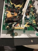
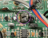
Looking for someone with a REL T5 to check voltages on the connection between the input board and the amp. There is a 4 pin connector going from the Amp to the Input board as pictured. I need to know the voltage of the power supplied to the input board. I assume its the Red and Black cables and the yellow and which are the signal inputs for the amp.
Help is appreciated.
Cheers,
Attachments
Bugger I've just fixed mine and re-assembled it.
I might take it apart again after this soak test but I would guess you are going to have +15V red, -15V black, yellow would be signal from the back board.
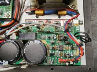
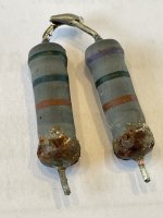
The two big black 2K2 resistors in your photo get hot and cook the nearby capacitors, from my photo I have mounted two metal 2K2 / 5W resistors on the heatsink so the heat goes out of the unit. These two resistors drop the +/-55V down to +/-15V along with two zener diodes.
What's wrong with yours?
Thanks
Michael
I might take it apart again after this soak test but I would guess you are going to have +15V red, -15V black, yellow would be signal from the back board.
The two big black 2K2 resistors in your photo get hot and cook the nearby capacitors, from my photo I have mounted two metal 2K2 / 5W resistors on the heatsink so the heat goes out of the unit. These two resistors drop the +/-55V down to +/-15V along with two zener diodes.
What's wrong with yours?
Thanks
Michael
Attachments
Hi Michael,
My unit was burning its fuse when a signal was sent to the amp board. when there is no input the amp would be on. As soon as a signal was sent via high/low or LFE it would burn the fuse. I found one of the resisters burnt and replace it and now it does not burn the fuse but there is not output from the amp. I suspect the input signal detection and turning on of the amp board may be the culprit.
When I first checked it was the red and black which seem to carry the signal and the yellow and white were carrying the power for some reason.
Any idea what would be wrong with my unit?
Cheers,
Hi,
On second look because I didn't look properly last time.
I am now looking at the attached photo and have zoomed into the top left.
Next to ISSUE:1.4 WAH JP1.
It looks like:
Black: Screen, 0V
Red: Signal
White: +15V
Yellow: -15V
Which resistor was burned?
If it blows a fuse then the fault is more likely to be on the bigger amp PCB.
I will take mine apart again in a few days and make some measurements for you.
Thanks
Michael
Attachments
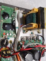
The resistor burnt was R230 located next to the blue VR abd directly above the two large 2.2k's.
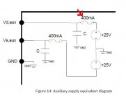
I have bought a ICEPower amp and trying to interface the input board. unfortunately, the secondary power output from the ICEPwr is +-25vdc.
in the meantime I think I burnt the +25v output. I have to find the built in fuse on the board and try to bypass it or put something to replace it.
If this is successful then I will try to interface the input board with the ICE amp.
so far I have not been able to get it going.
Attachments
The two in series resistors R230 had got cooked but I found they measured ok.
I will at some point get a 1K3 5W metal cased resistor mounted on the heatsink.
I think you should check the blue 200R VR201, I reckon by it's position it will probably read 66R.
Mine had died so I fitted a 220R and set it to 66R.
Well without the correct Q current values for the output transistors it will have to do...it does work.
Thanks
Michael
Sorry. The resistor that had got fried was R229 next to the 2 resisters on r230. also the Cap next to it was a bit discoloured so it may need changing as well.
As I said I'm trying to change to an ICEpower50ASX2BLT so that this eliminates the problem with the REL amps. I also have two REL Strata 3's I bought long time back. They too have similar issue's but I have managed to fix them. REL have started to use class d on the new S series so maybe its the way to go.
As I said I'm trying to change to an ICEpower50ASX2BLT so that this eliminates the problem with the REL amps. I also have two REL Strata 3's I bought long time back. They too have similar issue's but I have managed to fix them. REL have started to use class d on the new S series so maybe its the way to go.
I have eliminated the problems with mine, they won't happen again.
This unit is highly rated by Paul McGowan of PS audio as in many of his youtube videos.
I'm not sure he's actually been inside one and seen the bad practices.
The heat now goes straight to the heatsink and doesn't cook other components on the PCB.
Good luck.
Michael
This unit is highly rated by Paul McGowan of PS audio as in many of his youtube videos.
I'm not sure he's actually been inside one and seen the bad practices.
The heat now goes straight to the heatsink and doesn't cook other components on the PCB.
Good luck.
Michael
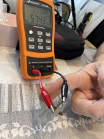
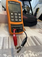
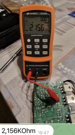
R230 I think is, See the measurements
Violet green Brown 750 ohm (738 tested)
Green Blue Brown 560 ohm (574 tested)
R229: have 2 check this later 4 u
Violet green Brown 750 ohm (738 tested)
Green Blue Brown 560 ohm (574 tested)
R229: have 2 check this later 4 u
Attachments

Replacement of the following parts on my REL T5 (appox. year 2005), subwoofer is now working again.

My T3 started blowing the fuse, nothing stands out visually, but it has that issue. Its for grabs free (including the 15ft neutrik cable) if anyone can fix it at home. And are local to the GTA. Rel wanted it shipped to California for repairs but I went another direction with it instead.
hello to all members
They gave me a damaged T5, after a storm, it stopped working
The owner took it to be repaired and the diagnosis was that the output transistors were damaged. They returned it without the transistor pads and with the transistors removed from the pcb (cut).
i will try to fix it
I have ordered all the capacitors and all the transistors to change them
resistor 229 is open, and vr201 is set at 135 ohms, I think it's wrong according to what I've read, does anyone know exactly how to adjust the correct bias of the output transistors?
thank you
I also needed the order of the transistors Q207,Q208,Q209,Q210
the ones I have are 2SB817 2SD1047, does anyone know the order on the pcb?
thank you
the ones I have are 2SB817 2SD1047, does anyone know the order on the pcb?
thank you
Im still considering turning t3's into t300's by swaping the OG drivers with 8" Ultimax Dayton.
It would either be a stupid mistake for screwing up perfect sounding tuneful subs by trying to obtain more SPLs.
In a perfect world they will sound great still, but with roughly double the slam.
Until they started to blow themselves apart??? Cabs are made well + braced but no steel hardware exists. They could hold up. I have had that happen though, but with a car sub box and Pheonix Gold sub + 1000 watts of HiFonics. Brute force.
Please share your findings and solutions with the community. This model is getting a little long in the tooth at a point plates have reached there life expectancy more or less. I imagine more to fix will be along.
I found a fix for one that didnt make sense dollar wise. It made more sense to grab my first class D crown with crossover and the bass journey continues.
That wakes em up to sound every bit as good as they do with the original amp / crossover. Keep in mind some rooms will stand to benefit with about 4 or 6db of boost. The one thing the crown lacks, eq. But thats often already there to deal with subs.
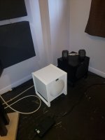
I stuck mine in a corner and it digs well and sound awesome, smashing if you prefer, as is. The bass is as tuneful and organic sounding as I could ask for.
I havent tried them in a stereo direct mode yet, on front R L yet, utilizing the left corner of room. But I believe it will further smooth response. Adding the outsider 10" so far works well. But cut off slopes vary a bit with media that has crazy low bass. The tiny rels dig impressively for being 8's with such tiny footprints. I dont notice much with most recordings. It still might be time to upsize cabs to 1.00. for the larger two however.
I found a fix for one that didnt make sense dollar wise. It made more sense to grab my first class D crown with crossover and the bass journey continues.
That wakes em up to sound every bit as good as they do with the original amp / crossover. Keep in mind some rooms will stand to benefit with about 4 or 6db of boost. The one thing the crown lacks, eq. But thats often already there to deal with subs.
I stuck mine in a corner and it digs well and sound awesome, smashing if you prefer, as is. The bass is as tuneful and organic sounding as I could ask for.
I havent tried them in a stereo direct mode yet, on front R L yet, utilizing the left corner of room. But I believe it will further smooth response. Adding the outsider 10" so far works well. But cut off slopes vary a bit with media that has crazy low bass. The tiny rels dig impressively for being 8's with such tiny footprints. I dont notice much with most recordings. It still might be time to upsize cabs to 1.00. for the larger two however.
Attachments
- Home
- Loudspeakers
- Subwoofers
- REL T5