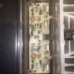
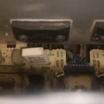
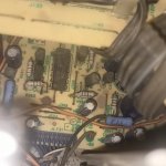
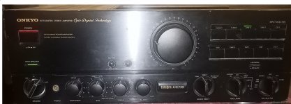
I am using this integra 817xd, seems to be in very good and works ok except that it produces crackling, intermittently, mostly on slow music. And as it was released in 1988, I suppose it should be now recapped, don't know what performance it might be holding back. Values and numbers of all parts are clearly visible, I need to find what parts to get as I think part to part replacement would not be available for this old amplifier. Haven't attached the pics for power section which has large capacitors and look good, thought first get through this tricky part. I am thinking about getting all the parts first and then take out the boards in one go for replacement. Will be uploading more pictures, might get some cheap endoscope camera to identify all the parts without opening the boards.
So where to start?
So where to start?
Attachments
-
 IMG20220131174058.jpg404.6 KB · Views: 337
 -
 IMG20220131174108.jpg400.3 KB · Views: 339
 -
 IMG20220131174126.jpg382.2 KB · Views: 296
 -
 IMG20220131174134.jpg243.9 KB · Views: 245
 -
 IMG20220131174140.jpg259 KB · Views: 275
 -
 IMG20220131174251.jpg335.2 KB · Views: 265
 -
 IMG20220131174300.jpg491.6 KB · Views: 257
 -
 IMG20220131174312.jpg223.7 KB · Views: 250
 -
 IMG20220131174329.jpg333 KB · Views: 263
 -
 IMG20220131174334.jpg348.4 KB · Views: 246
 -
 IMG20220131174720.jpg196.1 KB · Views: 229
 -
 IMG20220131174755.jpg521.1 KB · Views: 235
 -
 IMG202201311740431.jpg182.2 KB · Views: 308
some one suggested that this is similar to onyo A8690 https://www.diyaudio.com/community/threads/burning-hot-amp.215574/. Here is the schematic of A8690 attached.

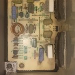
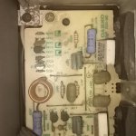
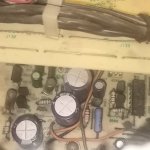
The one circled on the left is a 270 pico Farad styroflex capacitor the ones on the right could be something like polyethylene or polypropylene film capacitorsOr just help me identifying these capacitors type and brand too if possible.
My toughts:
- brand is not important in the sense that any today's good brand is good; you don't have to go for the same brand they used in 1988
- it is more important to match the value and voltage written on the old capacitors (for example I have not seen styroflex capacitors like the 270pF in new equipment, a sign that maybe is an obsolete technology)
- max voltage on the new capacitor can be higher than the max voltage of the old capacitor
- usually, the electrolytic capacitors are the ones that lose value (capacitance decreases) as they get older (even if they look good) so I would start with that.
- if you really want to change all capacitors then you should consider buying a multimeter than can measure capacitors
Last edited:
To floriant suggestions above, I would add NPO (COG) ceramic as safe choices for capacitor dielectric. Groner and Wurcer have shown this class of ceramic capacitors has excellent distortion performance.
- if you really want to change all capacitors then you should consider buying a multimeter than can measure capacitors
Thank you for identifying that, 1 down 2 to go, all are good suggestions, however, wont getting a capacitor measuring matter if I only wanted to replace the faulty ones?
You are right, that was selfish of me (smiling) I was hoping you will measure the old capacitors and post the results back here (in the interest of science!), like what percent of each category (styroflex, film, electrolytic) is still good (kept its value) after 34 years, thinking that would be useful information next time I have an old receiver in front of me and I want to replace only the "most likely to fail" ones. 🙂wont getting a capacitor measuring matter if I only wanted to replace the faulty ones?
IF electrolytic capacitor is warm without any signal being played does that mean it is not in direct signal path. Thinking of using Elna slimic II not in direct signal path and nichion FG and KZ at other places. due to better ripple current rating of elna, if it matters. Also what about capacitors in speaker protection circuit?
https://1drv.ms/b/s!Auv6QCaNgJiMkEbX5feQEWAu3FKK?e=KJ0ayt A890 schematic, almost same as 817xd except no DAC in 817xd.
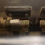
going through schematic in Power amp sec (II) resistors R603 AND R604 are 220 Ohms, but onboard R604 would measure in mega ohms and fluctuate, also on color band is red, black, grey color filled, brown, golden, and it seems it from factory as it is. So i have replaced it with 220 ohm. now Dc in speaker outputs reaches 1.5mv earlier it was zero. I was getting inconsistency in speaker output between both channels and still there is some present.
the problem at moment that is bothering me was even before replacing R604 220hm resistor and lot more so after it, the resistor at R903 and R904 (amp section I) are running untouchable hot, but amp seems to work fine. What can be causing these resistors to get that hot?
the problem at moment that is bothering me was even before replacing R604 220hm resistor and lot more so after it, the resistor at R903 and R904 (amp section I) are running untouchable hot, but amp seems to work fine. What can be causing these resistors to get that hot?
Attachments

Last edited:


I would never change any non electrolytic capacitor.
I would start cleaning switches, potansiometers & trimmers using a very good price cleaner solution.
Second i will look for empty or faulty electrolytics.
Hot resistors,as soon as they keep the value,aren't an indication of faults.
Measure old resistors out of the circuit.
You can' t use 1/4W resistors here.
If old resistors measure good, return those in the position.
If not,use 1W metal oxide.
Voltage drop resistors always run hot.
Last edited:
More important is that the voltage is as presented on the schematic; for example voltage on R903 is 58.4 - 47 = 11.4V , calculated dissipated power 0.4Wis bothering me ... the resistor at R903 and R904 (amp section I) are running untouchable hot
This is close to 1/2W specs and is tempting to change the resistor to 1W, but maybe it is intentionally like that close to the limit, in the sense that if something goes wrong and the current increase the resistor will burn (sacrifice resistors like fuses) and stop the damage to affect more components.
yes, I also think 1/2w is by design. here are voltages calculated with reference to chassis. before resistors 61.4, after R903 49.9, after R904 49.2. AC supply voltage is 105.5, amplifier is 100v rated. is 61.4 within tolerance are can something be wrong there?More important is that the voltage is as presented on the schematic; for example voltage on R903 is 58.4 - 47 = 11.4V , calculated dissipated power 0.4W
This is close to 1/2W specs and is tempting to change the resistor to 1W, but maybe it is intentionally like that close to the limit, in the sense that if something goes wrong and the current increase the resistor will burn (sacrifice resistors like fuses) and stop the damage to affect more components.
Last edited:
- Home
- Amplifiers
- Solid State
- 1988 Onkyo Integra 817xd recap and single channel crackling repair