Looking at various active crossover designs (especially ones found in cheap powered speakers) I noticed that they use SMD components, including capacitors.
I assume they use ceramic caps since SMD film caps look different and aren't that common. So how do they get away with it? I've always known that ceramic caps are a big no-no in the audio path.
I assume they use ceramic caps since SMD film caps look different and aren't that common. So how do they get away with it? I've always known that ceramic caps are a big no-no in the audio path.
Attachments


Not all ceramic caps are the same.
https://www.electronics-notes.com/a.../ceramic-dielectric-types-c0g-x7r-z5u-y5v.php
They also get away with it because good engineers follow physics, not magazine writers golden ears.
https://www.electronics-notes.com/a.../ceramic-dielectric-types-c0g-x7r-z5u-y5v.php
They also get away with it because good engineers follow physics, not magazine writers golden ears.
Your board have ceramic mlcc, probably X7R and X5R.
Some ceramic capacitor have huge variation with voltage, temperature and exhibit piezoelectric effect. In other words, using these where strong vibration - like inside active speakers - is a very bad idea.
But not all mlcc are the same. As many other things it is NOT good to generalise. C0G or also name NP0 capacitors can be used and perform well in audio. Of course they are big and expensive. 🙂
Also, X7R and X5R used at low signals levels can perform, let's say ... decent.
With some exceptions, Y5V, Z5U should not be used.
After all you get what you pay for.
Regards,
Tibi
Consumers don't hear/notice the difference... Its probably quite easy to detect from the poor measured THD at high volume. Note that there are dozens of ceramic material formulations used in MLCC's, some are worse than others, NP0 ad C0G grades are exemplary however, way more linear than the other grades as they cannot be made from paraelectric or ferroelectric materials.So how do they get away with it?
Non-para/ferroelectric ceramics have dielectric constants in the range 5 to 15 or so commonly, ferroelectric materials have (unstable) dielectric constants in the hundreds or thousands range. This is why they are compact, but less good. They tend to be strongly microphonic too.
The ferroelectric ones also have huge capacitance variations with voltage.
It is not uncommon for such a ceramic, specified as 22uF/50V to only be 22uF at 15V, and only 10uF at 35V, lower yet at 50V.
NPO / C0G are completely different and on a par with the best foil ones out there. But they are BIG. And relatively expensive.
Jan
It is not uncommon for such a ceramic, specified as 22uF/50V to only be 22uF at 15V, and only 10uF at 35V, lower yet at 50V.
NPO / C0G are completely different and on a par with the best foil ones out there. But they are BIG. And relatively expensive.
Jan
Panasonic make SMD foil capacitors (ECHUX, ECHU, ECPU, ECWUX etc.).
I actually made a crossover with them and it sounds good to me.
They are relatively expensive though and if I have the space I´d go for WIMA caps or so.
I actually made a crossover with them and it sounds good to me.
They are relatively expensive though and if I have the space I´d go for WIMA caps or so.
Bogdan2011: Are you finding any quality active xo's out there? I don't know anything about this company, but looks like they make active xo and other kits:
https://www.xkitz.com/collections/a...-way-active-crossover-fully-assembled-xover-2
You might ask them what types/tolerances they use for the frequency-setting resistors and capacitors, esp in the high pass section.
https://www.xkitz.com/collections/a...-way-active-crossover-fully-assembled-xover-2
You might ask them what types/tolerances they use for the frequency-setting resistors and capacitors, esp in the high pass section.
I am actually in the making of a active analog crossover design myself.
Currently writing a manual for it, but the board is basically done.
Like said before, on SMD boards you basically use NPO/C0G capacitors.
They are extremely stable, distortion levels usually same or better as film.
Sometimes they use film, but can be pretty pricey.
That being said, a lot of consumer electronics just use X7R and people don't really seem to care.
While i am no expert in smd, i even admit, i hate smd, i followed some clever guys web page how to improve the sound of classD amp (sure). It surely helped to replace input and output smd caps with regular mp. Significant drop in distortion, much more liquid sounding amp.
Those are PPS film, no foil involved.Panasonic make SMD foil capacitors (ECHUX, ECHU, ECPU, ECWUX etc.).
I actually made a crossover with them and it sounds good to me.
They are relatively expensive though and if I have the space I´d go for WIMA caps or so.
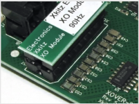
Well they say "Metalized Polypropylene Film capacitors with 2% precision", which I doubt judging by the picturesBogdan2011: Are you finding any quality active xo's out there? I don't know anything about this company, but looks like they make active xo and other kits:
https://www.xkitz.com/collections/a...-way-active-crossover-fully-assembled-xover-2
You might ask them what types/tolerances they use for the frequency-setting resistors and capacitors, esp in the high pass section.
X7R is pretty good, and NPO is excellent.
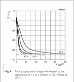
X7R is crap, especially the large values. See the picture for the capacitance versus voltage graph of a Murata 22 uF, 25 V, 1210, X7R capacitor. It's almost as awful as X5R.
100 nF, 25 V through-hole X7R; much better but still unusable if you want low distortion:
NP0 a.k.a. C0G is indeed excellent. Their graphs are just a straight horizontal line at 0 %.
X7R is crap, especially the large values. See the picture for the capacitance versus voltage graph of a Murata 22 uF, 25 V, 1210, X7R capacitor. It's almost as awful as X5R.
The trouble with calling X7R crap is there then isn't a word left to describe Z5U which is considerably worse.
Attached graph is for Z5U/Y5V in various voltages.
Attachments
Last edited:
X7R used for active filters will have a very small and almost constant voltage across. If you have a close look on the graf you will see that in area of 0V to 3-4V DC bias, the variation of capacitance is almost 0 and this is the voltage across it during normal operation when is used for active filters. So the problem of distortions generated by voltage variation because of capacitance variation is in fact a false problem if the schematic is well designed.
With signal voltages of the order of a few volts, I see changes of the order of 1 % in the best of the two graphs I posted. For instantaneous gain variations, when the gain is 1 % higher or lower in the signal peaks than in the bias point, you get a third harmonic distortion of about 1/24 % (Cherry's differential gain equations). In the case of a filter, the mathematics are more complicated, so this only serves as a rough order of magnitude estimate.
1/24 % is a lot compared to the distortion levels of just about any op-amp (LM324 and LM358 excepted). So all in all, the capacitors will dominate the distortion of the cross-over filter completely when you use class 2 ceramic capacitors (X7R, X5R, Z5U, Y5V, whatever).
1/24 % is a lot compared to the distortion levels of just about any op-amp (LM324 and LM358 excepted). So all in all, the capacitors will dominate the distortion of the cross-over filter completely when you use class 2 ceramic capacitors (X7R, X5R, Z5U, Y5V, whatever).
DC bias ain't the same thing as an AC voltage.
Usually the stability is seen from a capacitance vs temp graph.
But 22uF as a ceramic cap is kind of insane to begin with.
When absolutely necessary I would rather put two 10uF parallel or something.
Keep in mind that most respected manufacturers have no issue putting a bunch of simple and very ordinary electrolytic capacitors there instead.
So it's kind of relative.
But that value is totally not representative for an active filter. So also the claimed negatives are kind out if proportion.
(Exception is maybe a param EQ)
That's why my rough distortion estimate is based on the 100 nF data rather than the 22 uF data.
A non-linear but otherwise ideal capacitor doesn't see any difference at all between a DC voltage and a momentary voltage in a waveform. It just stores charge and sets a non-linear relation between the stored charge and the voltage across it, but it doesn't remember how long the charge/voltage has been there.
This isn't entirely true for a capacitor with dielectric absorption, but still, real life class II ceramic capacitors with dielectric absorption do distort. Just look at Cyril Bateman's classic articles about capacitor distortion.
Electrolytic capacitors distort far less than ceramic class II (or III) capacitors.
The caps are on the board, and the resistors are inside that xo module. Can you tell what type of caps those are from the picture?Well they say "Metalized Polypropylene Film capacitors with 2% precision", which I doubt judging by the pictures
Attachments
- Home
- Design & Build
- Parts
- SMD capacitors in active crossovers