Hello Guys!
After some years I would like to assemble a tube amp again. I would like to rebuild an "old" RCA circuit 1:1 and listen to it.
Now I have everything necessary for this at home. I see on the schematic that a feedback connection is hooked to the 16ohm connection of the OPT.
My OPT here has "only" an 8 Ohm output. My question to you tube experts: how do I have to adjust the values of the feedback parts so that it also works "correct" at 8 ohm ?
Your much appreciated help on this is higly welcome 😍
Should it fit if I reduce the R18 from 270 to about 220 ohms and increase the C6 from 0.01uF to 0.015uF and then connect to 8ohms?
That should then correspond approximately to the designed feedback values at 16Ohm? (280Ohm/0.01uF)
That should then correspond approximately to the designed feedback values at 16Ohm? (280Ohm/0.01uF)
In case the OPT is not exactly the same (Stancor 5k), I would begin with R18 = 270 ohms or even bigger and measure how much the GNFB is.
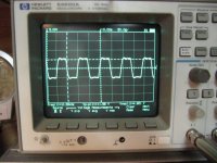
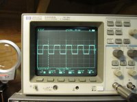
The value of C6 is best to determine with 10 kHz square wave input signal and adjust the value of C6 to optimum waveform.
The value of C6 is best to determine with 10 kHz square wave input signal and adjust the value of C6 to optimum waveform.
I would start with 180R for R18 - with C6, "tune" for best square wave response. Since the opt is in the feedback loop, its parasitic inductances and capacitances matter for the final value
ok, that means just leaving the R18 at the value as it is in the schematic and check the amplifier via square wave signal and then adjust the capacitor for best result, right?The smaller R18 is the higher is GNFB and instability problems are more likely.
You can leave the resistor how it is or change it for the input sensitivity you want .
The capacitor is adjusted like the an oscilloscope probe , to have 1KHz square wave as clean as possible , no overshoot or undershoot . And checking if the output signal ( sine wave ) is linear up to 20KHz .
The capacitor is adjusted like the an oscilloscope probe , to have 1KHz square wave as clean as possible , no overshoot or undershoot . And checking if the output signal ( sine wave ) is linear up to 20KHz .
10 kHz square wave is better for this adjustment and give more accurate result. Attached two photos of different transformer under this analysis.to have 1KHz square wave as clean as possible
It is obvious which one is better. The difference between these two transformers is more difficult to see if the test is done with 1 kHz square wave.
ok, that means just leaving the R18 at the value as it is in the schematic
I would measure the amount of GNFB, i.e. the difference of gain between open loop and closed loop condition. If the amount is between 12...17 dB, all is OK.
The fine tuning (upwards) can be done if the amount of THD is too high.
Attachments

How to do this? (Sorry I am not an expert in this)I would measure the amount of GNFB, i.e. the difference of gain between open loop and closed loop condition. If the amount is between 12...17 dB, all is OK.
The fine tuning (upwards) can be done if the amount of THD is too high.
This may not be that essential measurement, but it is done as follows:
The amount of GNFB is the ratio (in dB) between the two AC signals measured. Typically the value should be between 10...18 dB.
More than 18 dB will significantly increase possibility to instability. Less than 10 dB may cause too high output impedance and THD.
- terminate the amplifier to 8 ohms resistive load
- disconnect NFB from output transformer
- feed 1 kHz sine signal to the amplifier to get some 5...15 W output power (below clipping level)
- measure the AC voltage across the load
- connect NFB loop
- read the AC voltage across the load again
The amount of GNFB is the ratio (in dB) between the two AC signals measured. Typically the value should be between 10...18 dB.
More than 18 dB will significantly increase possibility to instability. Less than 10 dB may cause too high output impedance and THD.
Thank you!! 👍This may not be that essential measurement, but it is done as follows:
- terminate the amplifier to 8 ohms resistive load
- disconnect NFB from output transformer
- feed 1 kHz sine signal to the amplifier to get some 5...15 W output power (below clipping level)
- measure the AC voltage across the load
- connect NFB loop
- read the AC voltage across the load again
The amount of GNFB is the ratio (in dB) between the two AC signals measured. Typically the value should be between 10...18 dB.
More than 18 dB will significantly increase possibility to instability. Less than 10 dB may cause too high output impedance and THD.
True in general, but:The smaller R18 is the higher is GNFB and instability problems are more likely.
If you swap the NFB from the 16 Ω to the 8 Ω tap, or you replace the 16 Ω OPT by an 8 Ω one, the NFB voltage divider needs to be recalculated to keep close loop gain the same. In this case the upper resistor needs to be decreased appropriately.ok, that means just leaving the R18 at the value as it is in the schematic and check the amplifier via square wave signal and then adjust the capacitor for best result, right?
Best regards!
I think that since the OPT is not the same as in original RCA design, the GNFB should be lower in initial tests.
If there is no sign of instability then the GNFB can be increased.
If there is no sign of instability then the GNFB can be increased.
Another question I have is about the capacitors in this curcuit. Which type of C's would you use for C1,C2,C3,C4,C5,C6,C7 and C8? Use a electrolytic cap. for C3? All others FKP or MKP except the electrolytic C's (C9-C11, (C12)) in the power supply?
Note that C2 is given as 22uuF - that is not a typo - micro-micro farad means pico farad in our terms ... so C2 = 22pF.
Thx!Note that C2 is given as 22uuF - that is not a typo - micro-micro farad means pico farad in our terms ... so C2 = 22pF.
I am still unsure about the capacitors in this curcuit. The schematics shows everywhere electrolytic caps. Which kind of C's would you use especially
for C1,C2,C3,C4,C5,C6,C7 and C8? Use a electrolytic cap for C3?
Electrolytic C's (C9-C11, (C12)) in the power supply is clear.
for C1,C2,C3,C4,C5,C6,C7 and C8? Use a electrolytic cap for C3?
Electrolytic C's (C9-C11, (C12)) in the power supply is clear.
Sounds like a fun project. I hope you can get all the parts, without substituting.
7199, new old stock, are almost un-obtan-ium, or are responsible for bank-empty-um.
7027A, new old stock, may suffer from the same above problems.
In addition, finding ones that are very well matched is required; or you have to change the circuit to be able to match the plate currents (push pull output transformers do not like un-matched plate currents; it causes early saturation of the laminations).
The output stage can use either individual adjustable fixed g1 bias, or individual self bias resistors with individual bypass caps. That will provide for a way to match the output tube plate currents.
Overcome the above problems, and you should have a very good amplifier.
I recommend using 600V or 630V capacitors for the coupling caps from the 7199 triode to the 7027A grids.
20 x Log ((voltage out with no negative feedback) / (voltage out with negative feedback)) = dB of negative feedback.
Happy building! Happy listening!
Last edited:
1) Sounds like a fun project.
2) 7199
3) 7027A
4) .....self bias resistors with individual bypass caps.
1) yes5) I recommend using 600V or 630V capacitors for the coupling caps from the 7199 triode to the 7027A grids.
6) 20 x Log ((voltage out with no negative feedback) / (voltage out with negative feedback)) = dB of negative feedback.
2) i own a pair
3) i own quads from JJ. IDK if they are matched. I will build a uTacer3 tube curce tracer in the next weeks and try to check it there (utracer3 is a curve tracer and tube tester from Holland)
4) how to do it / can you guide me through to do a correct dimensioning the resistors please?
5) ok i have some here.
So C3,C9-C11 = electrolytic caps?
All other C's shown in the curcuit i.e wima mkp types?
6) ?
3) I was not aware that JJ made 7027A tubes.
4) From the family of tube curves (7027A); and your B+ voltage after it drops in the primary DCR, the plate voltages, plate current, the g1 bias voltage from the bias supply, and the cathode current.
You also have to estimate the screen current cathode current + screen current = cathode current.
Self bias voltage will lower the plate to cathode voltage, and it will lower the screen to cathode voltage.
I can not read the schematic and parts list.
But here is an example:
Suppose the g1 bias is 20 Volts, and the plate current is 40mA, and the screen current is 5mA.
Start with a self bias voltage of 20V. The cathode current, 40mA + 5 mA = 45mA (0.045A).
20V / 0.045A = 444 Ohms. But we lowered both the plate to cathode voltage and the screen to cathode voltage by the amount of the self bias voltage.
So use a resistor a little lower than 444 Ohms to bring the cathode current back to 45mA (try using 390 Ohm self bias resistors, one for each cathode).
Your amplifier from the RCA circuit may have different cathode current, and different g1 bias voltage; you have to determine that, and then find the appropriate quiescent current on the 7027 family of curves, and calculate the self bias resistor from those conditions.
5) The schematic is unreadable for me (can not read the C numbers, values, etc.).
That includes the coupling caps from the 7199 plate to the 7027 g1 grid circuit.
Do not use electrolytic caps for coupling caps.
6) In Post # 10, artosalo said: "The amount of GNFB is the ratio (in dB) between the two AC signals measured."
20 x Log of the Ratio of AC signal voltages (no negative feedback and with negative feedback). That = the dB of negative feedback.
The advice was to use at least 10dB and no more than 18dB of negative feedback.
- Home
- Amplifiers
- Tubes / Valves
- RCA tube amp (7199 & 7027A) 30W - NFB question