I'm in the journey of building my first tube amplifier. Well I'm rather close to the long-awaited end as everything's been soldered and tested (and it sounds sweet). The only thing I haven't managed to sort out is the heating for the power triode. The tube being a 300b requires a 5V at 1.3A or so current source, and I've decided to go with DC. I've bought several regulators (LT1805, LT1805-5IT, LM7805) and never had any luck: some would produce too low of a voltage (either due to overloading or low input voltage i believe), some would work briefly and then power off because of overheating, still producing too low of a voltage. The best I've been able to accomplish is ~4.3v with the LM7805 which still overheats and powers off. Now after a month or two of thinkering I've decided it's time to give up playing the guessing game and ask more knowledgeable people for a design.
In my current setup I take the 6.3V@4A secondary of my transformer (which powers two 6J5 using up about 0.6A of the total) and rectify it via a GBU4B, then filter it trough a 6800uF capacitor and feed it to one of the tested regulators. The rectified voltage at the filter cap is lower than what I expected (which may be the root cause for all my problems) ranging beetween 6.5-7.2 depending on the load. I'm afraid I may be putting too much stress on this winding and therefore getting a low rectified voltage, tough I've never seen the AC reading drop below (a very steady) 6.3V.
Things I though might help:
- Get some more efficient diodes (please leave suggestions if you have any)
- Use another small filament transformer just for this purpuse (I do have some space left to fit it)
- Add a heatsink for whatever regulator I end up using (I figure a 8°C/W one should be enough?)
Last edited:
I guess you could adapt this 6.3 Volt regulator to create 5 Volt.
https://www.diyaudio.com/community/threads/get-regulated-6-3-vdc-from-6-3vac.380957/
Regards, Gerrit
https://www.diyaudio.com/community/threads/get-regulated-6-3-vdc-from-6-3vac.380957/
Regards, Gerrit
As a general rule, if you need 1.25A DC, the filament transformer secondary AC current rating needs to be rated in the range of 1.65 to 1.8 times the DC load current (if you use a capacitor input filter; and you are not likely going to use a choke input filter on a filament DC supply, because the drop due to the choke input is 0.9 times the rms voltage, and does not even include the diode(s) voltage drop).
Refer to the Hammond data sheet that gives the DC current out, versus the AC secondary current rating.
It includes the factor (1.65 to 1.8) which is required for bridge rectifier and 2 lead secondary; and for a full wave center tapped secondary.
For examples, 6.3V and a bridge rectifier; and a center tapped 12.6V with a pair of diodes in full wave.
The full wave center tapped version only has one diode voltage drop, and the bridge has 2 diode drops.
Use Schottky diodes.
1.25A x 1.65 = 2.06 Amp rated secondary, required
1.25A x 1.8 = 2.25 A rated secondary, required
Use a secondary that at least is 2.5A AC rated.
Always check what the minimum burden voltage is on any regulator.
As an example, to give the concept, your regulator burden voltage and DCV to the regulator may vary:
If you get 6VDC from the rectifier and filter cap, and the regulator has a 0.8V burden voltage, that might work to get 5V out.
6VDC - 5VDC = 1V, large enough to meet the 0.8V burden voltage rating of the regulator.
But, if the ripple voltage to the regulator is +/- 0.3V, when the 6V drops to 6V - 0.3V, the regulator will drop below the required 0.8V of the regulator.
The 5V 1.25A 300B filament is 4 Ohms when the filament is warm.
But most Cold 300B filaments are less than 1 Ohm.
Some regulators will just put out their maximum current until the filament is warmed up (slowly) to 4 Ohms.
Other regulators will just "Give Up!" when presented with a 1 Ohm load.
Designing is both an art, and a science. Removal of either of those . . . you have a better chance at the Las Vegas Craps tables.
For my 300B single ended mono-block amplifier, I used a 6.3V 3.5A rated secondary (that old transformer was rated at either 115V or 117V in). The actual 6.3V was more like 6.8V when it was loaded with my 5V supply.
My mains power varies from 117 to 123VAC.
I used a very low drop Schottky bridge, a 22,000uF cap, a 2 Ohm power resistor to another 22,000uF cap, and that to the 5V 300B filament.
I adjusted the 2 Ohm resistor until the warmed up 300B filament was exactly at 5V, with the power mains at exactly 120VAC.
The 2 Ohm series resistor between the two filter caps is an automatic slow start on the filaments (300B filament ~ 1 Ohm cold, 4 Ohms warm).
The 300B filament was always within the WE filament voltage tolerance of +/- 5% of 5V, even when my power mains varied from 117VAC to 123VAC.
Brute Force works, if you do it right.
It does not get any simpler than that.
Regulators for the filament, not for me. I tried some over the years, and did not like them.
Just my opinions and experience.
Why don't you just go 5v AC? You're not building a phono preamplifier with300B...It's even safer to go AC for the fillament.No sudden current inrush either if you're using the right secondary winding thickness . With time you simply learn that tube manufacturers recommended ac voltages on tube fillaments in all datasheet for a reason...
If you still want to go 5v dc from 6.3v ac , schotky diodes followed by a capacitor multiplier with one trz or a darlington trz can be the simplest way to get it. Check luxman cl 34 service manual for a clear picture.
dreamth,
Please read my Post # 2 on this thread:
https://www.diyaudio.com/community/...ament-on-211se-how-quiet.381987/#post-691572545, 2A3, 300B, etc., All DHT, pick your tube.
Do you like your 2 X power mains frequency to appear as sidebands on each and every musical note and its natural harmonics of a musical instrument(s).
Intermodulation.
I did not worthlessly spend 50 years using spectrum analyzers and FFTs to measure sidebands on RF signals and Audio signals.
Please answer with some links of a few tube manufacturers of DHT tubes that recommend only AC to the filaments.
I agree with mcandmar:
A Rod Coleman regulator does work very well. I personally know of many in my area who use them.
dreamth,
Without a capacitor filter right after the rectifier, no capacitance multiplier is going to work.
Because, without a capacitor after the rectifier, the capacitance multiplier will see 0V at a rate of 2 X the Mains Power frequency.
What is the output of a capacitance multiplier when the voltage to it is 0V, 1V, 2V, etc. You can not get 5V out during those times of the power mains cycle. Capacitance multipliers act more like a regulator than they do a charge storing capacitor.
Regulators require DC in, even if that DC has a volt or 2 of ripple on it.
Just my 2 Cents
Is there any capacitor multiplier without a cap filter in front of it? Did i say anything about that?I indicated a schematic of a highly acclaimed commercial product...You could check it too.dreamth,
Without a capacitor filter right after the rectifier, no capacitance multiplier is going to work.
Just my 2 Cents
I don't believe anyone on anything before trying it myself if it's handy.I just saw the western electric datasheet .It clearly says AC or DC while in class A1...they specify just 5V AC .I don't think every application suffers of the same illnesses that can possibly be as most diabetics don't have AIDS...dreamth,
Please read my Post # 2 on this thread:
https://www.diyaudio.com/community/...ament-on-211se-how-quiet.381987/#post-691572545, 2A3, 300B, etc., All DHT, pick your tube.
Do you like your 2 X power mains frequency to appear as sidebands on each and every musical note and its natural harmonics of a musical instrument(s).
Intermodulation.
I did not worthlessly spend 50 years using spectrum analyzers and FFTs to measure sidebands on RF signals and Audio signals.
Please answer with some links of a few tube manufacturers of DHT tubes that recommend only AC to the filaments.
Actually it's not that simple if you don't have a steady minimum 7.2v input voltage at the needed power.
dreamth,
A. We have many newbies reading these threads.
1. You said: " 5v dc from 6.3v ac , schotky diodes followed by a capacitor multiplier".
2. I say: 6.3VAC, "schottky diodes followed by a capacitor, and then followed by a capacitor multiplier".
Newbies sometimes take things literally. 1. and 2. are different.
Listing an amplifier that is unknown to newbies; and then not posting a link to the schematic is not kind to them.
Just my newbie friendly opinion.
B. You said: "I don't believe anyone on anything before trying it myself if it's handy."
True, if you do not have a proper spectrum analyzer or FFT, it is not handy.
But those of us who do have a proper spectrum analyzer or FFT use them (for very good reasons).
So, get yourself a spectrum analyzer that can measure Audio frequencies, or a good scope FFT.
Take a 300B amplifier, use AC filaments. Apply a 1kHz sine wave to put out 70% voltage, 1/2 power, (-3dB referenced to amplifier's full rated output).
You will see those sidebands.
50Hz power mains: 900Hz lower sideband, 1kHz test tone, 1100Hz upper sideband.
60Hz power mains: 880Hz lower sideband, 1kHz test tone, 1120Hz upper sideband.
Or . . . do not look for those sidebands by using a spectrum analyzer or FFT, because what you do not look for is not there, right?
Just my opinion and experience.
I'm not sure if this is a place for newbies...Have you seen the warning when you access any page in this section of the forum?
I ignored a similar one for a while way before going into high voltage industry and i got electrocuted with 500v dc...burned the skin on a hand...unfortunately mine ...I don't need to feel that tragic, honestly especially about other's measurement equipment.I used both Audio precision system one and two not too much ...just enough to know how useless it is with valve circuits and in general ...If it's anything there to worry about you'll hear it.
A spectrum analyzer can see a lot of things we don't hear, but we listen the music with our ears first. I simply advised for the simplest way to make the thing work .
Google is anyone's friend...newbie or not...and typing in the name of an equipment plus the word "schematic" will promptly show several places for schematics.
https://elektrotanya.com/luxman_cl34_sch.pdf/download.html
Thanks for all the suggestions, that really gave me some food for thought. Unfortunately the plan was to use DC filaments from the start so I will be ditching the idea of using AC.
I've especially appreciated all the info 6A3sUMMER shared here. So these are solutions applicable to my amplifier, in order of preference:
I've especially appreciated all the info 6A3sUMMER shared here. So these are solutions applicable to my amplifier, in order of preference:
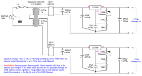
- 6.3V AC from my current transformer -> skotchy bridge -> filter cap (either the one I have or another) -> LT1085 regulator as shown below.
This option is assuming the skotchy bridge gives me enough voltage to drive the regulator circuitry as with my current bridge recitfier the voltage is too low. (How does this schematic look to you?) - 6.3V AC from my current transformer -> rectified and dropped with resistor the brute force way. This option is extremely simple which I like, but I've never checked how much the mains voltage vary in my home. Being in Italy, EU enforcement guarantee ±10% which is way too high of a variation for the DC supply but also for the high voltage supply. In practice the percentage is definitely lower and I'd have to measure it. None the less this is a great second option.
- Add another transformer and buy Rod Coleman boards which I've heard great things about, but with the chassis being done and everything mounted I don't have too much space for the transformer, the board and some heat sinks which I guess will be required.
Attachments
For 1.3A DC, the RMS current in the PT is ca. 2.5A, and the peak current is ca. 7A.
A 2.5A PT is not enough - you need an extra margin, to allow for the peak current.
This may be the reason why you didn't get enough DC voltage....
I recommend at least 4A, preferably 5A or even more. The PT is more likely to buzz, if the rating is too low.
You can use a 6.3V PT to feed my new V9 regulators for 300B; message for info.
You may wanna read this: https://www.diyaudio.com/community/threads/get-regulated-6-3-vdc-from-6-3vac.380957/
1. Newbies,
How many of you are avid readers, who read threads like this, even though you will not build an amplifier like this as a first amplifier?
You just want to learn as much as you can, before you begin building an even simpler amplifier, right?
2. Spectrum analyzers and FFTs Do measure many things that we Can Hear, they do not only measure things that we can not hear.
Even a digital scope with only an 8 bit FFT can measure things that you can hear.
Never discount the value of a measurement tool, especially if you are in the middle of the Pacific ocean, and the Captain wants that broken electronic gear fixed now, if not sooner.
Boy, how I wish I had today's simplest digital scope and FFT when I was in the middle of the Pacific.
3. There are more dead US Navy sailors that died from 110VAC than from any other voltage.
500V AC or DC is not safe.
110AC is not safe.
Safety First, whether you are experienced, or whether you are a Newbie.
Prevent the 'Surviving Spouse Syndrome'.
Just my opinions, and just my experience.
Last edited:
78xx regulators are only good for up to 1.5 amps, maybe 2 amps if you push it.
But doesn't anybody here know or have the experience with the widely-known and quite simple way to boost their current capability by adding a hefty TO3 type transistor?
I won't post any schematics of such things, that's for you to do.
But doesn't anybody here know or have the experience with the widely-known and quite simple way to boost their current capability by adding a hefty TO3 type transistor?
I won't post any schematics of such things, that's for you to do.
Do not forget, the cold resistance of the 300B is less than 1 Ohm (<1 Ohm).
Any regulator, IC, T03 bipolar / MOSFET, or combination thereof, has to be able to not burn out, oscillate, or fold-back to zero current, when it drives the cold filament resistance.
Ask me how I know.
You get 3 guesses, and the first 2 do not count.
Any regulator, IC, T03 bipolar / MOSFET, or combination thereof, has to be able to not burn out, oscillate, or fold-back to zero current, when it drives the cold filament resistance.
Ask me how I know.
You get 3 guesses, and the first 2 do not count.
No original 78xx will die if overcurrent is asked from it.
No 78xx will work here properly because it doesn't have enough input voltage especially with an emitter follower booster.
A low drop regulator might accomodate an emitter follower though.
For some weird reason everyone feels offended when somebody else has a different idea lately.
I'd use a resonant converter to get both fillament and high voltage supply from a cheap 12v smps anytime although for a serious project a resonant converter based on a specialised IC working straight on the mains grid might be a more proper choice.Never tried that yet.
Here's my last year developpment of the concept with the help of Dave who suggested me a miraculous circuit after my first bipolar Baxendall resonant inverters trials on high voltage forum.
I especially recommend those guys for high voltage design experience if not used to do it.
https://highvoltageforum.net/index.php?topic=1439.msg10989#msg10989
Here's my Luxman cl 34 clone using its last embodiment...I used a 12 v Sony Play station 2 supply for trials.In the mean time i found that ebay offers many r-core transformers having both low and high voltages for tube equipment and a classical approach is always simpler.
Attachments
- Home
- Amplifiers
- Tubes / Valves
- 5V regulated supply