I have a Kenwood 5-channel that turns on for a second and then turns right back off. Nothing seems to be burnt that I can see.
Any help would be greatly apricated.

Any help would be greatly apricated.
Do you see a pulse of DC on any of the bridging speaker terminals or on the positive terminal of the sub channel between the time remote is applied and the time when the amp shuts off?
I do see a pulse of about .5vdc on the bridging terminals and about a volt down to .3vdc on the sub positive.Do you see a pulse of DC on any of the bridging speaker terminals or on the positive terminal of the sub channel between the time remote is applied and the time when the amp shuts off?
The output transistors would be Q818, Q816, Q814, Q812, Q815, Q813, Q811, Q817? If so they they are not shorted.
No it is next on my list to purchase.
No it is next on my list to purchase.
Was it doing this in the car?
After it shuts down, Measure and post the DC voltage on all terminals of the TL494. Copy and paste the following list and fill in the blanks.
Pin 1:
Pin 2:
Pin 3:
Pin 4:
Pin 5:
Pin 6:
Pin 7:
Pin 8:
Pin 9:
Pin 10:
Pin 11:
Pin 12:
Pin 13:
Pin 14:
Pin 15:
Pin 16:
After it shuts down, Measure and post the DC voltage on all terminals of the TL494. Copy and paste the following list and fill in the blanks.
Pin 1:
Pin 2:
Pin 3:
Pin 4:
Pin 5:
Pin 6:
Pin 7:
Pin 8:
Pin 9:
Pin 10:
Pin 11:
Pin 12:
Pin 13:
Pin 14:
Pin 15:
Pin 16:
Someone gave me the amp. Not sure what it was doing in the car.Was it doing this in the car?
After it shuts down, Measure and post the DC voltage on all terminals of the TL494. Copy and paste the following list and fill in the blanks.
Pin 1: 0.01vdc
Pin 2: 5.02vdc
Pin 3: 4.61vdc
Pin 4: 1.18vdc
Pin 5: 1.48vdc
Pin 6: 3.67vdc
Pin 7: 0.001vdc
Pin 8: 13.41vdc
Pin 9: 0.001vdc
Pin 10: 0.001vdc
Pin 11: 13.44vdc
Pin 12: 13.44vdc
Pin 13: 5.02vdc
Pin 14: 5.02vdc
Pin 15: 5.02vdc
Pin 16: 9.32vdc
What are you using to power this amp?
Do you see any red adhesive around the perimeter of any of the SMD components?
Do you see any red adhesive around the perimeter of any of the SMD components?
Iam using a little 12vdc regulated power supply.What are you using to power this amp?
Do you see any red adhesive around the perimeter of any of the SMD components?
No I don't see any red adhesive.
Lift (as shown below) Q841. Will the amp try to power up?
I recommend having all heatsink mounted transistors tightly clamped to the heatsink when you apply power. Since this will defeat part of the protection circuit, be ready to remove power if the amp begins to draw excessive current.
Does the amp power up normally?
I recommend having all heatsink mounted transistors tightly clamped to the heatsink when you apply power. Since this will defeat part of the protection circuit, be ready to remove power if the amp begins to draw excessive current.
Does the amp power up normally?
Attachments
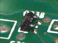
It dose power up and stay on.Lift (as shown below) Q841. Will the amp try to power up?
I recommend having all heatsink mounted transistors tightly clamped to the heatsink when you apply power. Since this will defeat part of the protection circuit, be ready to remove power if the amp begins to draw excessive current.
Does the amp power up normally?
I damaged it trying to get it lifted. What would a replacement be? I also lifted a pad with it what's the best way to repair it?
Do you read anything more than a fraction of a voltage of DC across the two speaker terminals for any of the 5 channels?
In the future, if you have to lift a transistor like that, apply additional solder to both terminals so the iron can heat both at the same time and then lift when the solder is molten.
An exact replacement would be the best replacement.
In the future, if you have to lift a transistor like that, apply additional solder to both terminals so the iron can heat both at the same time and then lift when the solder is molten.
An exact replacement would be the best replacement.
Only one is likely shorted. Remove one of them and recheck both.
You may be able to tell (both in the board) which is bad by finding the one with the lowest resistance gate to drain.
Install the one that's still good (be sure to remove all solder bridges from the pads of the missing FET) and see if there is still DC across the sub output terminals.
You may be able to tell (both in the board) which is bad by finding the one with the lowest resistance gate to drain.
Install the one that's still good (be sure to remove all solder bridges from the pads of the missing FET) and see if there is still DC across the sub output terminals.
Last edited:
There is just minimal voltage on it now less then half a volt. I removed Q320 that was the faulty one it is a b31n20d. I cant find a in stock replacement. Any recommendations? Also will need a replacement for Q841.Only one is likely shorted. Remove one of them and recheck both.
You may be able to tell (both in the board) which is bad by finding the one with the lowest resistance gate to drain.
Install the one that's still good (be sure to remove all solder bridges from the pads of the missing FET) and see if there is still DC across the sub output terminals.
Thank you
I don't know where you're located so I can't recommend electronics distributors.
The IRFB31N20D is obsolete. Any you find may be counterfeit. The IRF640 or IRF640N may be a suitable replacement. You must replace both the defective FET and the one that was parallel with it.
Does the sub channel now produce audio?
The IRFB31N20D is obsolete. Any you find may be counterfeit. The IRF640 or IRF640N may be a suitable replacement. You must replace both the defective FET and the one that was parallel with it.
Does the sub channel now produce audio?
- Home
- General Interest
- Car Audio
- Kenwood KAC-7005PS Problem