In a recent foray into the rabbit hole of DIY slit cones, I came upon a post by Pete Basel bringing up Mark McKenzie's methods of controlling cone breakup. His site is no longer up since 2019, and Archive.org contains no images for the archives before 2005 which contain his Tangband and other driver mods which appeared very successful in neutralizing cone modes.
That method is mainly dimples placed in specially selected locations on the speaker cone. From what I gather this was very effective on paper and polypropylene cones but not on metal cones. The way of deciding on the position was dependent on cone vibration measurement techniques which I don't think he ever disclosed, although he mentions laser measurements. How to interpret those measurements to find optimal locations is not necessarily obvious itself.
About the same time (2004-2008) the EnABL concept was also proliferating. The important difference to me is that I have seen little success in attempts to measure the difference made by EnABL treatment, while there is quite lot of impulse response and frequency response results given by McKenzie. While both treatments are said to sound good, I lean toward the McKenzie treatment because there are also clear measurements of improved driver behavior.
I suspect McKenzie's mods didn't catch on because to DIYers, working under the permission of a patent holder in order to complete a crude project in one's own garage is somewhat grating, some would even say degrading. At the same time it would be nice to have seen McKenzie have some material success with his ideas or earn something from his valuable work.
But oddly what we see instead is that there are hardly any images of anything he ever created. This is odd for something which clearly shows great promise. What is certain is that his patent has been respected as I haven't seen any dimple cones in commercial offerings (although my searches are limited). There are slit cones, ribbed cones, textured cones and embossed cones, but not dimple cones. Is anyone allowed to benefit from this distressingly simple and effective technology?
Here is mcKenzie's patent US20070092101A1:
https://patents.google.com/patent/US20070092101A1/en?oq=20070092101
For a circle of dimples placed on the cone, I can see in my mind the dimples reliving the circumferential compression of the cone as the center deflects forward in response to the voicecoil. I think the cone would deform in a sort of 1920s faceted gramophone horn like shape. I suspect a lot of this has to do with relieving that circumferential compression and stretching of the cone as the most nonlinear behavior of any membrane is the difference between tensile and compressive strength. Paper cones tend to remind me of the sound of a curved sheet of printer paper being bent and then snapping back into shape.
Okay, I have one critical thought. dimples may break up the resonance modes of the cone itself but what happens at higher levels where nonlinear effects occur? I suspect the local stress concentrations of the dimples could actually worsen cone performance at high sound levels. Then again it could just as easily be argued that they reduce stress on the cone by controlling resonances and so improve performance. Maybe somewhere in between is the truth, depending on how well the concept is executed.
Can we reconstruct McKenzie's work from what remains? He wrote articles for AudioXpress and he even posted on this forum between 2004 and 2008. But most of his forum images, in fact almost any image he ever made, are lost. Is McKenzie still with us?
https://www.diyaudio.com/community/threads/markmcks-tang-band-mods.28355/
Apparently at one time he sold mad3 and mad6.5 drivers as well as others, but I can't find anything about them either.
I just found a capture of his site on the wayback machine that does preserve some images:
http://web.archive.org/web/20050307073039/http://madspeaker.com:80/index.htm
Apparently there are two versions of his website on the wayback machine. The other one is here:
http://web.archive.org/web/20200121101523/http://madspeaker.com/index.html
Last edited by a moderator:
Thanks for bringing all this back to life: I was unaware of the fact MarkMcK used to post here as well. That being said: there is suprisingly little hard and practival diy info or tips 'n tricks of a more general nature. JBruner seems to -practically speaking- bring a lot more to the table with his SB and PE driver mods.
Yes, it is worth mentioning the original thread where I fell into this rabbit hole, as it has basically the same goal as McKenzie's mods:
https://techtalk.parts-express.com/forum/tech-talk-forum/66754-how-to-train-your-pm180-8
It is the best documented result of a DIY slit cone modification that I can find, others did not necessarily turn out so well.
McKenzie's site had pages telling us how to apply the mods to several drivers, which counts in my book, pity there are not enough images preserved to understand what to do.
Without knocking the significant work that went in, glancing across the claims made in the patent, I'm a mite surprised it actually got through, as I can't really see anything that couldn't be called well-established prior practice by DIYers & manufacturers. Or I would be, but for the fact that a lot of things do get patented which really shouldn't as it seems to be quite easy to pull the wool over examiners eyes, especially non-specialists.
Ultimately, it depends what you're trying to do: like the other thread you started, there is no single solution as the issues addressed vary from design to design, both in terms of objectives and their physical properties. And you've got to keep the nature of the driver in mind. Something like, say, a magnesium cone Seas Excel, or (more cheaply) an aluminium cone Dayton RS180 or RS225 are specifically optimised for pistonic operation over a relatively narrow operating BW, accepting significant bell-modes above that, where they are not intended to be used. Slapping a bunch of targeted damping (for example) on those may reduce their amplitude, but is to completely miss the point of the driver, and misuse them into the bargain as you'll likely be sacrificing their positive attributes just to obtain mediocre gains elsewhere. Strategic damping of excess resonances on wideband driver cones (since many operate using controlled TL modes) can be effective, but to do it properly, you'll need to measure & unless you have a lot of equipment unavailable to most DIYers, engage in quite a bit of empirical experimenting & FR, impedance etc. measurements to establish what provides what you consider to be a good compromise of attributes for a given drive unit. The final itterations (note caveat) of the EnABL process, where Bud and Dave were physically listening for cone modes and placing their block rings at those points, is one example of that -plenty of others. The big Bastanis units have felt dots, powdered crystals, doping & a bunch of others things applied IIRC. And you can include edge-damping of soft-cone resonances in that too, where the damn things start to go out of phase due to lack of rigidity & put a notch in the response, usually in the 800Hz - 1.6KHz region etc. Lots of examples, very little (basically none) of which are in any way recent.
Ultimately, it depends what you're trying to do: like the other thread you started, there is no single solution as the issues addressed vary from design to design, both in terms of objectives and their physical properties. And you've got to keep the nature of the driver in mind. Something like, say, a magnesium cone Seas Excel, or (more cheaply) an aluminium cone Dayton RS180 or RS225 are specifically optimised for pistonic operation over a relatively narrow operating BW, accepting significant bell-modes above that, where they are not intended to be used. Slapping a bunch of targeted damping (for example) on those may reduce their amplitude, but is to completely miss the point of the driver, and misuse them into the bargain as you'll likely be sacrificing their positive attributes just to obtain mediocre gains elsewhere. Strategic damping of excess resonances on wideband driver cones (since many operate using controlled TL modes) can be effective, but to do it properly, you'll need to measure & unless you have a lot of equipment unavailable to most DIYers, engage in quite a bit of empirical experimenting & FR, impedance etc. measurements to establish what provides what you consider to be a good compromise of attributes for a given drive unit. The final itterations (note caveat) of the EnABL process, where Bud and Dave were physically listening for cone modes and placing their block rings at those points, is one example of that -plenty of others. The big Bastanis units have felt dots, powdered crystals, doping & a bunch of others things applied IIRC. And you can include edge-damping of soft-cone resonances in that too, where the damn things start to go out of phase due to lack of rigidity & put a notch in the response, usually in the 800Hz - 1.6KHz region etc. Lots of examples, very little (basically none) of which are in any way recent.
All good points. I was also thinking that when you force a woofer to play into the midrange, you also accept the midrange modulation due to the excursion of the bass. The more into the ear sensitive region the woofer is used, the more apparent and audible this is likely to be. So it might not be a good idea to do this for woofers that were not designed with midrange use in mind.
That said, McKenzie is clear about tackling the largest contributors to audible inaccuracy first and he maintains that inductance modulation is quite secondary to the evils of cone modes, so he was not immediately concerned with it although he acknowledged it would probably be audible in certain cases. He seemed content to let someone else take on that project.
There are also implications for sound radiation pattern that come with cone mode treatment that might be worth considering.
Personally the largest issue for my B652-Air speakers was the 3.4KHz resonance of the woofer, fixing that had to come before all else. The B652 is a cheap speaker yes, but actually the woofer seems pretty well controlled in my measurements aside from 3.4KHz. The magnet is small and some distortion is measurable but my experience follows McKenzie's that the B652 is much better with the woofer peak controlled.
Here is a short and sweet thread about one of Mark's driver modifications:
https://www.diyaudio.com/community/threads/pe-299-145-buyout-5-25-ppcone.41380/
If the midbass unit is being run up into the region where you have obvious issues, then sure, addressing that is going to bring benefits. Likewise if you have insufficient suppression of stopband modes in the crossover of a multiway (assuming they are sufficient to amplify distortion in the passband). If the design does not allow those to be addressed in the filter for various reasons, then mechanical mods are the way forward. Mechanical solutions to mechanical problems is usually favourite, assuming they can be achieved successfully, otherwise filter changes may be preferable as at least you know they can be reversed. 😉 For conventional multiways (wideband drivers, horns and coaxes have different sets of priorities & approaches) my normal preference these days is to only run the drivers in their piston range, which eliminates most of the potential problems, although does tend to require relatively complex filtering. My most recent 2-way design for e.g. has a 19 element filter; if the caps get charge-coupled (possible) that may end up as either 20 or 25, depending on whether you class the 6 diodes as a single or independent components.
In that vein McKenzie points out that even if you notch out a cone mode, harmonics will still be amplified if they hit the cone mode and also the off-axis response will still suffer from the resonant dispersion pattern, which is apparent in the measurements of the slit cone PM180 in post #3.
Mechanically controlling the cone resonance solves these issues.
Mechanically controlling the cone resonance solves these issues.
To add some background to that last link to McKenzie's modifications in post #5, the discussion on inductance modulation is missing some key mechanics of how the motor works. McKenzie misses out on the fact that inside the motor, the voicecoil inductance at HF is actually less than it would be with no motor, due to the skin depth of eddy currents in the pole plate and pole piece being smaller than their diameter at HF. So the coil inductance does need to be decreased at HF outside the motor. However at low frequencies where the eddy currents do not short out the magnetization of the steel parts, the coil inductance actually is larger inside the motor as you would expect. So outside the motor, the coil inductance needs to be increased at LF and decreased at HF in order to linearize it for all frequencies across the excursion range. The simplest way to do this is an extended pole piece. A tophat shaped polepiece has also been used as well as an aluminum or copper cap on top of the extended pole piece and other variations. What is common knowledge now was apparently not at time the discussion was taking place so like all historical material, it must be understood in the context in which it occurred. I suspect McKenzie would appreciate this little bit of historical philosophy.
So do many others, but in fact they are wrong. You can, with specific techniques, kill the distortion amplification in the crossover, as a number of people, myself included, do in a number of designs. If you prefer not to believe me, you can ask Yevgeniy over at Hificompass, who will confirm. Where people often go wrong is in believing that if they simply suppress a resonance to match a given LP rolloff target, that is automatically sufficient. Unfortunately, it usually isn't.In that vein McKenzie points out that even if you notch out a cone mode, harmonics will still be amplified if they hit the cone mode and also the off-axis response will still suffer from the resonant dispersion pattern, which is apparent in the measurements of the slit cone PM180 in post #3.
Mechanically controlling the cone resonance solves these issues.
As for the off-axis, as I noted, my preference with conventional (by 'modern' parlance) multiway designs is to only use the drive units within their piston BW, which generally mandates low, high order crossovers, so their behavior in the chaotic region is in essence neither here nor there as it is heavily suppressed before it reaches that point.
Yeah, patents are odd things. I gave up trying to figure out how some of them make it through a while back, although linguistic sleight of hand often seems to play a part. 😉
Not necessarily, but as noted you've got to be prepared to be brutal with the filtering, and it isn't always possible; depends on your objects and the drivers of course. The design I mentioned above for e.g. is a 2-way, LR6 at 1KHz (more or less), and with 19 electrical elements & somewhat more physical components to hit the target values, power-handling etc., I suspect it's a mite 'excessive' for many in terms of cost, complexity etc. And of course, for those who philosophically prefer lower order slopes, or a more 'elegant' approach to crossover design, it's a non-starter.
Not necessarily, but as noted you've got to be prepared to be brutal with the filtering, and it isn't always possible; depends on your objects and the drivers of course. The design I mentioned above for e.g. is a 2-way, LR6 at 1KHz (more or less), and with 19 electrical elements & somewhat more physical components to hit the target values, power-handling etc., I suspect it's a mite 'excessive' for many in terms of cost, complexity etc. And of course, for those who philosophically prefer lower order slopes, or a more 'elegant' approach to crossover design, it's a non-starter.
I'm listening. All I can think of is a series notch filter which increases the impedance seen by the woofer at the mode frequency and reduces re-entrant flux modulation distortion, resembling current drive at that frequency.So do many others, but in fact they are wrong. You can, with specific techniques, kill the distortion amplification in the crossover, as a number of people, myself included, do in a number of designs.
The Bodzio Ultimate Equalizer site has some pictures of advanced notching & what it can achieve.
What I noticed - with the help of fellow member DonvK- is one needs sometimes 8th order (or even higher order) digital notches to equalize seemingly innocent i.e lower order peaks. A double passive LCR lid goes an long way, but for perfect removal of a peak sometimes more brute force is needed. EqualizerAPO does a wonderful job here.
What I noticed - with the help of fellow member DonvK- is one needs sometimes 8th order (or even higher order) digital notches to equalize seemingly innocent i.e lower order peaks. A double passive LCR lid goes an long way, but for perfect removal of a peak sometimes more brute force is needed. EqualizerAPO does a wonderful job here.
Rather than ask anyone to believe me (since they don't until they go elsewhere and check), I'll directly quote Yevgeniy of hificompass:I'm listening. All I can think of is a series notch filter which increases the impedance seen by the woofer at the mode frequency and reduces re-entrant flux modulation distortion, resembling current drive at that frequency.
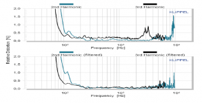
Yes, of course. The notch can down 3rd and 5th HD peaks corresponding to the breakup resonance as much as the peak is attenuated. This distortion is born in a speaker's motor and manifests itself as a distortion voltage source in the voice coil circuit. This voltage source creates the voice coil current, which drives the voice coil and is subjected to the resonance amplification by the cone at the breakup frequency. You need to break circuit for voice coil curent at breakup frequency by adding hi-impedance notch in series with the voice coil. It really works.
An example of where Accuton used to do just that in their own datasheets attached, and also the popular Tafal 2-way, which notches the tweeter's ultrasonic resonance, significantly reducing measured HD in the passband. This is something a few of us occasionally do, and can work rather well. As they say, 'the measurements don't lie'. 😉 End of story.
Attachments
Yevgeniy seems to corroborate my theory, but your example with the parallel filter implies different mechanisms. When the source of distortion is coil excursion rather than hysteresis, there seems to be an optimal series resistance to minimize distortion. In woofers this may be on the order of say 2 ohms, not normally attainable because the coil resistance is already 3 or 6 ohms. Maybe something similar is at play in your case.
You'll have to ask Yevgeniy if he can supply filter details from his own measurements I'm afraid. The ones I posted above are respectively Accuton's own, which they occasionally used to add to some data sheets (but stopped doing so a while ago, for some reason), and those available in the Tafal writeup, which I converted into an animated gif for convenient comparison. If I get to my store over the next few days, I'll try to pull some of my own measurements from the HDD & post them then (the laptop I use is still there, since these days I rent a suitable space from them as required when testing). The notches in question for both the above BTW are as stated / referenced: parallel notches in series with the coil, i.e. drive unit.
Last edited:
Depends what you define as 'basic', since depending on crossover frequency, target slope &c. you have to account for those as relevant in the transfer functions & overall response, along with the impedance load, since in most cases you don't want it to be too reactive unless you're certain you've got an amplifier with sufficient headroom. Bottomless / zero pole is usually preferable given the objectives, though depending on the overall shape of the breakup mode & exactly what you're doing, some resistance on one or other of the components may be beneficial. In some cases, you can apply as-is if they're correctly tuned & sufficiently outside the transition band not to mess up the overall frequency & phase responses. If that's not the case, then as noted you need to build them into the transfer functions from the outset, and that, as you know, can get a mite more complex. 😉
Last edited by a moderator:
No worries Scott: I have worked with LCR circuits in combination with optimizers since 1989 in Calsod 1.3, and later IMP/M+ Calsod 3.0, which software did not like to optimize LCR circuits. Once fed with proper ARTA made .frd and .zma files LSPCad did the job in 5 seconds 7-8 years later.
- Home
- Loudspeakers
- Full Range
- Does anything remain of Mark McKenzie's dimple cones and madsound?