Quick run down:
Batt died because vehicle sat awhile
Attempted to jumo it with a schumacher battery starter, batt was too low so I just attached it to batt and used the charge feature.
Maybe coincidence but after car was recharged radio was dead, nothing happens when pressing ON button.
-Checked fuses, all good.
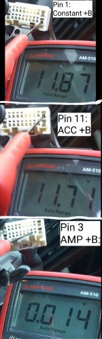
-Removed HU to probe connector, pins 1 and 11 supplied +12v constant and 12V when key turned to ACC ON, continuity between GND and body, good.
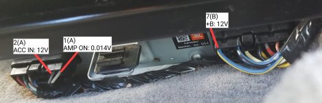
-Probed amp coNnector, 12v constant + 12v acc on is good. Continuity between GND pin and car body, good.
-Took HU to the bench, supplied pins 1 and 11 with +12VDC, try to turn on radio and nothing
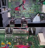
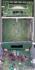
-disassemble HU, remove CD Player/Changer + Tape deck to inspect main board.
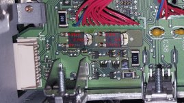
-Notice slight heat discoloration near power transistor area, focused on two TO-252 (DPAK) 7256's
-Probe for V on Dpak, 12V on one (not sure what part of dpak is called but its the middle/main tab), ~3V on the other
-Probe face plate, confirm volume/on pot has continuity when button is depressed. Then verified it has voltage.
-probed various other areas and noted it in pictures attached.
Any clue what couldve caused this issue?
Worried if I replace the HU with another one it may cause damage again to HU.
I assume fixing this without schematic/parts list may be a foolish task?
p.s. I have higher resolution versions of my images if itd be helpful, just let me know
Thanks for your time gentlemen.
Will update if I figure out more
Batt died because vehicle sat awhile
Attempted to jumo it with a schumacher battery starter, batt was too low so I just attached it to batt and used the charge feature.
Maybe coincidence but after car was recharged radio was dead, nothing happens when pressing ON button.
-Checked fuses, all good.
-Removed HU to probe connector, pins 1 and 11 supplied +12v constant and 12V when key turned to ACC ON, continuity between GND and body, good.
-Probed amp coNnector, 12v constant + 12v acc on is good. Continuity between GND pin and car body, good.
-Took HU to the bench, supplied pins 1 and 11 with +12VDC, try to turn on radio and nothing
-disassemble HU, remove CD Player/Changer + Tape deck to inspect main board.
-Notice slight heat discoloration near power transistor area, focused on two TO-252 (DPAK) 7256's
-Probe for V on Dpak, 12V on one (not sure what part of dpak is called but its the middle/main tab), ~3V on the other
-Probe face plate, confirm volume/on pot has continuity when button is depressed. Then verified it has voltage.
-probed various other areas and noted it in pictures attached.
Any clue what couldve caused this issue?
Worried if I replace the HU with another one it may cause damage again to HU.
I assume fixing this without schematic/parts list may be a foolish task?
p.s. I have higher resolution versions of my images if itd be helpful, just let me know
Thanks for your time gentlemen.
Will update if I figure out more
Attachments
-
 radioConnector_R2.jpg191.7 KB · Views: 163
 -
 jblAmpConnectors_resize_32.jpg193.8 KB · Views: 194
 -
 wireDiagram.jpg232.9 KB · Views: 188
 -
 viewsOnTransistorHotArea.jpg725.7 KB · Views: 186
 -
 probedVoltages_mainboard+faceboard_resize_4.jpg540.9 KB · Views: 151
 -
 faceplateV.jpg369.2 KB · Views: 159
 -
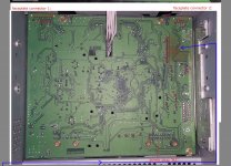 mainBoard_traceSide.jpg564 KB · Views: 172
 -
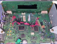 mainBoard_componentSide.jpg725.9 KB · Views: 195
The tab of the transistor is generally the drain or collector.
The thermal damage to the board looks like long-term damage. This is generally due to insufficient heatsinking.
Do you have a scope?
Use the various numbers on the case of the head unit to search for a service manual on the following site:
https://elektrotanya.com/?q=keres
Thanks for being so thorough and posting in a way that was easy to read.
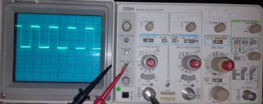
Yes I have a tektronix 2213A that I have 'restored' with some help online in the past. It also had similar board discoloration due to beam focus resistors that stay hot over time.
I have various probes/clips etc, just have never really used it before aside from looking at signals from a signal generator.
Im kind of a newbie who just happens to have all the tools and some understanding of how to not blow them up or shock myself.
I'll check that site, will be shocked to find it, will update with any findings.
Thanks, I figured my pics would be more so confusing and annoying haha -- I have ran into a ton of poor pictures when lurking forums though so I think I know what ya mean.
Attachments

Probe various pins on the keyboard and the pins of the microcontroller. Do you see any pulses on any of those pins?
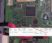
Is the microcontroller the chip on the backside of the face plate board? Or one of the chips on the mainboard?
By keyboard pins I assume you mean what I have labelled as Faceplate Connector #1 and 2?
I will look up pulses now to see what I need to look for then will pull out the scope, excited to finally use it on something.
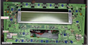
pic attached is rear side of faceplate board (not the best pic)
By keyboard pins I assume you mean what I have labelled as Faceplate Connector #1 and 2?
I will look up pulses now to see what I need to look for then will pull out the scope, excited to finally use it on something.
pic attached is rear side of faceplate board (not the best pic)
Attachments

The IC above is likely the display driver/controller. The main control IC is likely the one between J5 anf the white label.
Thanks Perry, about to grab the scope now.
I was curious in regards to safety, will it be acceptable to connect probe to ground (such as chasis) if im powering the device with a 2 pronged wallwart as shown below top right?
Or should I swap the 2 prong wallwart for my 3 pronged one that is 12VDC 5A?
A bit of a ghetto power solution until I buy a real lab supply, apologies.
Attachments

Either should work but most wall-warts have a 1-shot fuse that when blown may not be replaceable. The slightest mistake overloading it or allowing the wires to touch will kill it.
I'd use the 5A supply.
The scope has a 3-prong plug so the grounds for the supply and the scope will be connected through the mains ground. If you need a better ground for more critical measurements, you can ground the scope probe to the case of the head unit.
I'd use the 5A supply.
The scope has a 3-prong plug so the grounds for the supply and the scope will be connected through the mains ground. If you need a better ground for more critical measurements, you can ground the scope probe to the case of the head unit.
Spent most of the day reading up on how to check for pulses and using the scope.
I believe I may have done something wrong because most of the wave outputs were the same, even if I probed the chassis.
I used the 12v 5A 'three pronged' power supply + 10x probe (without ground lead)
The microcontroller pins were too small, worried I may short them so I probed at near by via pads (I think that is valid?)
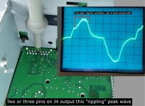
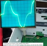
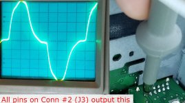
The only areas that output a different wave were a few of the pins on the face plate connectors (J2 and J3) as pictured.
I observed no movement of the waves except for a couple pins on Face Connector 1 (J4) that showed slight ripple on one area of wave as pictured.
----
I re-checked voltage in a few areas, my initial post was incorrect, both DPAK have voltages but they're not the same.
Note: (L) in the picture denotes that the voltage started lowering slowly while I had the probe on it.
I believe I may have done something wrong because most of the wave outputs were the same, even if I probed the chassis.
I used the 12v 5A 'three pronged' power supply + 10x probe (without ground lead)
The microcontroller pins were too small, worried I may short them so I probed at near by via pads (I think that is valid?)
The only areas that output a different wave were a few of the pins on the face plate connectors (J2 and J3) as pictured.
I observed no movement of the waves except for a couple pins on Face Connector 1 (J4) that showed slight ripple on one area of wave as pictured.
----
I re-checked voltage in a few areas, my initial post was incorrect, both DPAK have voltages but they're not the same.
Note: (L) in the picture denotes that the voltage started lowering slowly while I had the probe on it.
Attachments
It sounds like there is an open ground in either the scope or the power supply. You can use either the probe ground to the case of the head unit or use a wire to connect the 12v supply output ground to the scope ground terminal (on the face of the scope).
You were correct, clipping probe lead GND to case of HU solved the problem.
I believe the HU is the issue because I notice when touching chasis that reading measurements with DMM previously wasn't accurate until I removed skin from chasis.
----
I checked keyboard connectors (J3 and J4) as well as the pins/vias connected to MCU (N60 MASK chip), I didn't notice any pulses -- I believe a pulse would be the line on the graticule jumping to a different DCV and then returning to baseline?
The closest thing to a pulse I found was that the DCV baseline would jump up ONLY when I pressed buttons and on/off switch on the keyboard.
The DCV would rise to a new DCV and stay steady as long as I held the button, then return to baseline when button was released.
This happened on some of the keyboard connector (J3 + J4) pins.
Pulses on the microcontroller will generally be a constant train. If there are no pulses, the controller could be damaged or missing supply voltage. The generic datasheet for the IC may be useful for the supply pins.
I see, a train is similar to the output of the 'probe adjust' wave. I should've been able to see them with scope set to DC, 10x probe from 2-10V/DIV and 1-.5ms/div instead of just a flat line, based on what i'm reading in this .pdf I found.
I tried looking up the IC, the closest I could find was from a 'Car Radio Database' site which gave a return on the CPU but it wasn't the exact same number of CPU. I tried looking up both numbers and multiple search strings with no datasheet to be found for this CPU.
I wonder if it's a proprietary chip with no datasheet to be found?
Tried searching various search strings of the numbers found on the chip:
N60 MASK
09392882
(I think the next two lines are date code or serials)
0205KEA05
23194R
Attachments
Some head units have security where they won't allow stolen head units to be used but I've never seen one that gave no indication of any life.
Have you tried posting this on a forum dedicated to your vehicle to see if they could provide any insight?
Have you tried posting this on a forum dedicated to your vehicle to see if they could provide any insight?
Yes, i've also searched old forum posts and multiple users informed that the AD6900 (this particular toyota HU) doesn't have anti theft system.
I've also had the car's battery out for awhile and I believe it's died a couple times in the past from sitting too long and neither events triggered an ATS.
I've also had the car's battery out for awhile and I believe it's died a couple times in the past from sitting too long and neither events triggered an ATS.
Don't take me wrong but this is a very strange approach to fault finding but....
The EEprom can store loads of things from firmware, security code and so on and it is done for over 20 years in all sorts of electronic devices.
Wish you good luck
The EEprom can store loads of things from firmware, security code and so on and it is done for over 20 years in all sorts of electronic devices.
Wish you good luck
I may be wrong because i'm quite a novice but I believe Perry's logic is to see if the CPU is functioning, if not, is it being supplied voltage at proper pins (which is what datasheet would be for).fault finding
I assume when the HU is functioning normally (i.e. turns on when you press PWR button) that the CPU is sending pulses even before you press the "PWR" button?
If you have any suggestions and the time, please feel free to let me know if you have any ideas. It's on the bench!
When the HU is off the cpu/mcu is in sleep/stand by mode and needs a pulse from the "On" circuit to wake up.
The first think to diagnose is to check if the HU is actually been feed with the required voltages like 12V, 5V, 3.3V and then go from there.
Need to go out will be back in around 2 hours
The first think to diagnose is to check if the HU is actually been feed with the required voltages like 12V, 5V, 3.3V and then go from there.
Need to go out will be back in around 2 hours
It's being supplied 12V on the two input pins. The mainboard and faceplate board do have voltages.required voltages like 12V, 5V, 3.3V
No schematic available and i'm not experienced enough to know what to expect where.
Have been tinkering with it and showed what pins had what voltages via pics attached to the above posts.
- Home
- General Interest
- Car Audio
- 02 Avalon OEM JBL + Amp 7 spkr - Any idea what caused this damage to HU?