I’ve been testing various options for creating a clean and stable 6.3 Volt DC from the 6.3 Volt AC heater transformer winding. Why DC? I discovered earlier that DC on the driver tube’s heaters did lower the residual hum and noise of my tube amplifier. Even though the hum was inaudible I could still measure some.
Therefore I use DC for two 6SN7 tubes per channel in my amplifier. This means each channel draws 1.2 A average heater current, with of course a current surge for cold tubes when switched on.
Of course this solution can be used for lots of other tubes with a 6.3 volt heater.
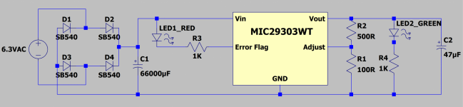
I started with rectifying the AC voltage with a full Schottky bridge, using SB540 diodes. These fast switching diodes can do 5 A up to 28 Volts AC RMS with a voltage drop of approximately 480 mV with full load. The bridge is feeding 3 capacitors of 22000 uF each (66000 uF in total).
Of course I could use the raw voltage for the 6SN7 heaters. But I wanted to do better than that, by adding some sort of regulation.
I tried with a LT1084 regulator at first, because I had them lying around. With 1.2 A load, the voltage dropped to 6.2 Volt. This will work quite OK, but we’re at the limit of the LT1084 as far as regulation is concerned.
Next I tried a XL6009 DC-DC Step-up boost converter, as sold very cheap on Aliexpress and Ebay. It worked for a while, but the output voltage can only be set with the appropriate load. This means when you only have one of the two tubes inserted for whatever reason, the remaining tube will get a lot more than 6.3 Volt. I further noticed the output voltage was not always stable. On these cheap boards the XL6009 chip is not cooled, so there we have another issue. I abandoned the idea of using two of these cheap boards in this project.
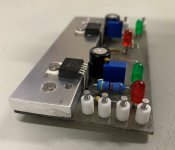
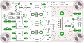
Then I came across the Microchip MIC29303WT Low Drop regulators. I bought mine from Mouser and made a prototype PCB for two regulators on a single heat sink. The heat sink is just a piece of thick aluminium.
The MIC29303WT is the adjustable type of the MIC29XXX range, with a current rating of max. 3 A. It’s using a 5 pin TO220 package. For adjustability I added a 500 Ohm potentiometer (R1 in the datasheet and in the diagram below). The combination of this variable resistor and the 100 Ohm fixed resistor (R2) is just enough minimum load to get a stable output voltage. According to the datasheet we should expect approximately a 250 to 300 mV voltage drop with a 1.5 A load. Not bad for such a cheap device!
Due to the cold tubes current surge I use two regulators, one for two 6SN7 tubes.
The MIC29303WT has an Error Flag connection, which signals output out-of-regulation. It can sink up to 10 mA, so I added a LED with a resistor in series to make use of this option. The LED blinks when the unit is switched on and off, so it’s working! I also added a green LED to show that the output voltage is present.
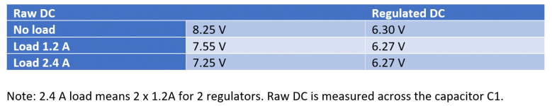
The most important thing is of course if we get the 6.3 Volt DC? And does it regulate properly? I made some measurements and the results are even better than expected.
Not shown in the schematic diagram, but visible on the picture is a 47 Kohm resistor. This is added to allow heater elevation by elevating the minus contact of this board to a voltage of approximately 40 volts from the main power supply.
I also tried to make some basis measurements for residual AC (hum/noise) on the output. Unfortunately I had quite long measuring leads, so I measured 0.6 mV with the power off. When I switch the power on I cannot measure any increase of the AC. I haven’t had time yet to make further measurements with my spectrum analyzer.
Happy DIY!
Gerrit
Therefore I use DC for two 6SN7 tubes per channel in my amplifier. This means each channel draws 1.2 A average heater current, with of course a current surge for cold tubes when switched on.
Of course this solution can be used for lots of other tubes with a 6.3 volt heater.
I started with rectifying the AC voltage with a full Schottky bridge, using SB540 diodes. These fast switching diodes can do 5 A up to 28 Volts AC RMS with a voltage drop of approximately 480 mV with full load. The bridge is feeding 3 capacitors of 22000 uF each (66000 uF in total).
Of course I could use the raw voltage for the 6SN7 heaters. But I wanted to do better than that, by adding some sort of regulation.
I tried with a LT1084 regulator at first, because I had them lying around. With 1.2 A load, the voltage dropped to 6.2 Volt. This will work quite OK, but we’re at the limit of the LT1084 as far as regulation is concerned.
Next I tried a XL6009 DC-DC Step-up boost converter, as sold very cheap on Aliexpress and Ebay. It worked for a while, but the output voltage can only be set with the appropriate load. This means when you only have one of the two tubes inserted for whatever reason, the remaining tube will get a lot more than 6.3 Volt. I further noticed the output voltage was not always stable. On these cheap boards the XL6009 chip is not cooled, so there we have another issue. I abandoned the idea of using two of these cheap boards in this project.
Then I came across the Microchip MIC29303WT Low Drop regulators. I bought mine from Mouser and made a prototype PCB for two regulators on a single heat sink. The heat sink is just a piece of thick aluminium.
The MIC29303WT is the adjustable type of the MIC29XXX range, with a current rating of max. 3 A. It’s using a 5 pin TO220 package. For adjustability I added a 500 Ohm potentiometer (R1 in the datasheet and in the diagram below). The combination of this variable resistor and the 100 Ohm fixed resistor (R2) is just enough minimum load to get a stable output voltage. According to the datasheet we should expect approximately a 250 to 300 mV voltage drop with a 1.5 A load. Not bad for such a cheap device!
Due to the cold tubes current surge I use two regulators, one for two 6SN7 tubes.
The MIC29303WT has an Error Flag connection, which signals output out-of-regulation. It can sink up to 10 mA, so I added a LED with a resistor in series to make use of this option. The LED blinks when the unit is switched on and off, so it’s working! I also added a green LED to show that the output voltage is present.
The most important thing is of course if we get the 6.3 Volt DC? And does it regulate properly? I made some measurements and the results are even better than expected.
Not shown in the schematic diagram, but visible on the picture is a 47 Kohm resistor. This is added to allow heater elevation by elevating the minus contact of this board to a voltage of approximately 40 volts from the main power supply.
I also tried to make some basis measurements for residual AC (hum/noise) on the output. Unfortunately I had quite long measuring leads, so I measured 0.6 mV with the power off. When I switch the power on I cannot measure any increase of the AC. I haven’t had time yet to make further measurements with my spectrum analyzer.
Happy DIY!
Gerrit
Attachments

A Battery Powered Differential Probe on your SA would help a lot. I've been using one now for about 20 yrs with
the various PicoScope SA's I have.
the various PicoScope SA's I have.
Following the "new normal", first wasted space, THEN the answer

---------------------------------------------------------------------------------------------------------
Sorry for adding useful or at least related content below.
---------------------------------------------------------------------------------------------------------
Not so sure what this achieves. [2]
Given rectified 6.3V AC is so close to desired 6.3V DC it definitely complicates matters and is barely achieved; problem is it requires HERCULEAN effort for a not-so-necessary result.
* Schottky diodes? Check. No big deal so why not.
* 66000uF filtering? 😵 😱 You-must-be-joking.
---------------------------------------------------------------------------------------------------------
---------------------------------------------------------------------------------------------------------
Not so sure what this achieves. [2]
Given rectified 6.3V AC is so close to desired 6.3V DC it definitely complicates matters and is barely achieved; problem is it requires HERCULEAN effort for a not-so-necessary result.
* Schottky diodes? Check. No big deal so why not.
* 66000uF filtering? 😵 😱 You-must-be-joking.
Hi, I do this for years as it works fine. Schottky diodes are a must in this case just like large caps (66,000 µF is overdone 😉). The MIC regs are simply noisy and a slightly better choice also because of lower dropout voltage in real life (at 3A....) is the LT1764.
The build is impressive to me!I’ve been testing various options for creating a clean and stable 6.3 Volt DC from the 6.3 Volt AC heater transformer winding. Why DC? I discovered earlier that DC on the driver tube’s heaters did lower the residual hum and noise of my tube amplifier. Even though the hum was inaudible I could still measure some.
Therefore I use DC for two 6SN7 tubes per channel in my amplifier. This means each channel draws 1.2 A average heater current, with of course a current surge for cold tubes when switched on.
Of course this solution can be used for lots of other tubes with a 6.3 volt heater.
I started with rectifying the AC voltage with a full Schottky bridge, using SB540 diodes. These fast switching diodes can do 5 A up to 28 Volts AC RMS with a voltage drop of approximately 480 mV with full load. The bridge is feeding 3 capacitors of 22000 uF each (66000 uF in total).
Of course I could use the raw voltage for the 6SN7 heaters. But I wanted to do better than that, by adding some sort of regulation.
I tried with a LT1084 regulator at first, because I had them lying around. With 1.2 A load, the voltage dropped to 6.2 Volt. This will work quite OK, but we’re at the limit of the LT1084 as far as regulation is concerned.
Next I tried a XL6009 DC-DC Step-up boost converter, as sold very cheap on Aliexpress and Ebay. It worked for a while, but the output voltage can only be set with the appropriate load. This means when you only have one of the two tubes inserted for whatever reason, the remaining tube will get a lot more than 6.3 Volt. I further noticed the output voltage was not always stable. On these cheap boards the XL6009 chip is not cooled, so there we have another issue. I abandoned the idea of using two of these cheap boards in this project.
Then I came across the Microchip MIC29303WT Low Drop regulators. I bought mine from Mouser and made a prototype PCB for two regulators on a single heat sink. The heat sink is just a piece of thick aluminium.
The MIC29303WT is the adjustable type of the MIC29XXX range, with a current rating of max. 3 A. It’s using a 5 pin TO220 package. For adjustability I added a 500 Ohm potentiometer (R1 in the datasheet and in the diagram below). The combination of this variable resistor and the 100 Ohm fixed resistor (R2) is just enough minimum load to get a stable output voltage. According to the datasheet we should expect approximately a 250 to 300 mV voltage drop with a 1.5 A load. Not bad for such a cheap device!
Due to the cold tubes current surge I use two regulators, one for two 6SN7 tubes.
The MIC29303WT has an Error Flag connection, which signals output out-of-regulation. It can sink up to 10 mA, so I added a LED with a resistor in series to make use of this option. The LED blinks when the unit is switched on and off, so it’s working! I also added a green LED to show that the output voltage is present.
The most important thing is of course if we get the 6.3 Volt DC? And does it regulate properly? I made some measurements and the results are even better than expected.
Not shown in the schematic diagram, but visible on the picture is a 47 Kohm resistor. This is added to allow heater elevation by elevating the minus contact of this board to a voltage of approximately 40 volts from the main power supply.
I also tried to make some basis measurements for residual AC (hum/noise) on the output. Unfortunately I had quite long measuring leads, so I measured 0.6 mV with the power off. When I switch the power on I cannot measure any increase of the AC. I haven’t had time yet to make further measurements with my spectrum analyzer.
Happy DIY!
Gerrit
Ive made something similar with the MIC5156 before, i chose this part because it allows for driving a really big low RSDon mosfet. the downside is added complexity in furnishing the driver supply.
Attachments
That looks good. Please mind that a version exists with internal charge pump (so no added complexity).
theres more than one way to rome, i like this because the dropout can be made as low as your pass fet RSDON allows. and apart from the 2 euro controller there is nothing special on the board.
you do have to derate the AC/DC conversion by quite a bit, because charge peaks are heavy in this module.
Something is wrong with the forum, i cannot upload the schematic. Its too big apparently
you do have to derate the AC/DC conversion by quite a bit, because charge peaks are heavy in this module.
Something is wrong with the forum, i cannot upload the schematic. Its too big apparently
I meant MIC5157 which is essentially the same but it creates its own extra power supply so even less parts. Which MOSFET did you use?
And ... what do you mean with "charge peaks"? That is because of using large filter caps?!
And ... what do you mean with "charge peaks"? That is because of using large filter caps?!
RFP12N10L it works well, with very low noise. TME does not carry the 5157 which was my reason to stick with the 5156. the downside is that you need a logic level FET if you are furnishing the supply from 6VAC
If you want lower dropout an IRFZ44n may work well.
If you want lower dropout an IRFZ44n may work well.
I havent found it to be the case actually, the doubler is high impedance, and i run it into a 220uF cap with a RC. measured noise is well below 200uV for this module. i should cut out the zener diode as it appearantly is allready baked into the 5156 for the mosfet driver supply.
Mmmm maybe I don't understand what you mean. I haven't had much issues but MOSFETs had to be chosen with care. What was the challenge was to have enough filtered voltage with small ripple.
I misread your post, and thought you said noise due to the voltage doubler, im using 30000uF or 30mF for filtering, and depending on applied source there is about 7.5V to play with. plenty for 2.5A of output current, leaving some reserve for low mains situations.
You could parallel two skottkey diodes for an added 150mV headroom or thereabouts. or go to a 10A die, but those are rare.
You could parallel two skottkey diodes for an added 150mV headroom or thereabouts. or go to a 10A die, but those are rare.
Gerrit, slightly OT: where did you get those nice (Teflon?) turrets?I’ve been testing various options for creating a clean and stable 6.3 Volt DC from the 6.3 Volt AC heater transformer winding.
[ ... ]
Gerrit
Jan
Hi Jan,
I created them from larger Teflon turrets with a sharp knife. They are actually somewhat longer, but I now prefer my own shorter version.
I found them on Marktplaats, seller “Tauritronics”. I bought quite a few of them a couple of times.
Regards, Gerrit
I created them from larger Teflon turrets with a sharp knife. They are actually somewhat longer, but I now prefer my own shorter version.
I found them on Marktplaats, seller “Tauritronics”. I bought quite a few of them a couple of times.
Regards, Gerrit
Wanting 6,3V DC from 6,3V AC without doubler ... in bad days with lower mains it is guaranted that the regulation will be lost 
Or maybe for small tubes you should want 6V or lower ... which could improve noise and tube's life .
Or maybe for small tubes you should want 6V or lower ... which could improve noise and tube's life .
Hi Depanatoru,
If you look at my measurements I still have 1 Volt left to play with. In other words, a mains drop will not affect the regulation, it will only lower the power dissipation in the regulator. With Schottky diodes and a MIC29303 you will not need a doubler.
Regards, Gerrit
If you look at my measurements I still have 1 Volt left to play with. In other words, a mains drop will not affect the regulation, it will only lower the power dissipation in the regulator. With Schottky diodes and a MIC29303 you will not need a doubler.
Regards, Gerrit
- Home
- Amplifiers
- Tubes / Valves
- Get regulated 6.3 VDC from 6.3VAC