Hey guys,
During the years I have built a couple of speakers based on Beyma 8CX300Nd/N and found it a good-sounding driver all in all. Recently, I decided to revise the crossover design for this driver to get the best sound possible. I built a cabinet by laminating BB plywood and took some actual measurement with it and simulated it in Xsim and VituixCAD and both are pretty similar, but I was hoping to get flatter response, that's because I'm writing about it here to hear your opinions if this could be done any better.
The cabinet is a bass reflex with ~30l volume and there is down-firing port underneath.


I measured the woofer near-field response and also the far-field and merged them about 250hz. Then I measured port near-field response and compensated it according to its surface area and added it to woofer response. Then simulated the baffle step diffraction loss and imported it as a graph into REW and multiplied it to the overall response of the woofer:

here is the tweeter @1m. I was hoping the tweeter will perform better but...

Here is the simulation in Xsim using the actual FRD and ZMA in the cabinet. First I wanted to use the woofer response after subtracting the baffle step diffraction loss, but then I decided to ignore it by taking the room gain in lower frequencies into consideration:


And here is the VituixCAD simulation:


Actually, I'm happy with the woofer flatness, but the tweeter is so so and doesn't seem it can get any better than this. Any idea to get a better result is much appreciated.
During the years I have built a couple of speakers based on Beyma 8CX300Nd/N and found it a good-sounding driver all in all. Recently, I decided to revise the crossover design for this driver to get the best sound possible. I built a cabinet by laminating BB plywood and took some actual measurement with it and simulated it in Xsim and VituixCAD and both are pretty similar, but I was hoping to get flatter response, that's because I'm writing about it here to hear your opinions if this could be done any better.
The cabinet is a bass reflex with ~30l volume and there is down-firing port underneath.
I measured the woofer near-field response and also the far-field and merged them about 250hz. Then I measured port near-field response and compensated it according to its surface area and added it to woofer response. Then simulated the baffle step diffraction loss and imported it as a graph into REW and multiplied it to the overall response of the woofer:
here is the tweeter @1m. I was hoping the tweeter will perform better but...
Here is the simulation in Xsim using the actual FRD and ZMA in the cabinet. First I wanted to use the woofer response after subtracting the baffle step diffraction loss, but then I decided to ignore it by taking the room gain in lower frequencies into consideration:
And here is the VituixCAD simulation:
Actually, I'm happy with the woofer flatness, but the tweeter is so so and doesn't seem it can get any better than this. Any idea to get a better result is much appreciated.
Surely you wouldn't need to add the simulated bafflestep response if you're already working with real, in-box measurements, as they would already include that effect?
Nice work. How do they sound?
Maybe the tweeter horn is just a bit too hot ... maybe take it down 1-3 db?
I would guess the bit ragged response is due to the horn and the diffraction at the edges, and reflection from the woofer and cabinet.
If you look at how this is improved in the Danley Studio 1, you have the unit mounted on the back of the baffle and the front forming the "missing" part of the horn.
Air from the woofer is pressed through holes in the horn and at the circumference btw baffle and horn ... very synergy like (Innovative thinkin from Danley 🙂 )
I would guess one could even make this more pronounced in e.g. the horizontal plane and less in the vertical, letting more air out under and over the horn ...
I see you have made a beautiful cabinet already, so maybe starting by making some kind of wings could maybe be a start
Attachments

Hi Dave,
I can't help you with passive crossover but here are my thoughts. It seems for me and the work I put down on my coax, that the peaks around 2 and 4,5kHz needs to be adressed. Also the elevation between 500-1000Hertz needs to be flattened. I had roughly the same issues as you, when these peaks were fixed and getting a general down sloping response, all seemed to be heading into a clearer sound. I don't have a recent measure, but attached is after getting peaks down and this shows before fixing the elevation around crossover, all done by DSP. I think this is as good as it gets with a coax, for me it sounds good, despite the unevenness... People seems to "listen" to graph's today;o)

I can't help you with passive crossover but here are my thoughts. It seems for me and the work I put down on my coax, that the peaks around 2 and 4,5kHz needs to be adressed. Also the elevation between 500-1000Hertz needs to be flattened. I had roughly the same issues as you, when these peaks were fixed and getting a general down sloping response, all seemed to be heading into a clearer sound. I don't have a recent measure, but attached is after getting peaks down and this shows before fixing the elevation around crossover, all done by DSP. I think this is as good as it gets with a coax, for me it sounds good, despite the unevenness... People seems to "listen" to graph's today;o)
Surely you wouldn't need to add the simulated bafflestep response if you're already working with real, in-box measurements, as they would already include that effect?
Sure. that's right. thanks,
Nice work. How do they sound?
Maybe the tweeter horn is just a bit too hot ... maybe take it down 1-3 db?
I would guess the bit ragged response is due to the horn and the diffraction at the edges, and reflection from the woofer and cabinet.
If you look at how this is improved in the Danley Studio 1, you have the unit mounted on the back of the baffle and the front forming the "missing" part of the horn.
Air from the woofer is pressed through holes in the horn and at the circumference btw baffle and horn ... very synergy like (Innovative thinkin from Danley 🙂 )
I would guess one could even make this more pronounced in e.g. the horizontal plane and less in the vertical, letting more air out under and over the horn ...
I see you have made a beautiful cabinet already, so maybe starting by making some kind of wings could maybe be a start
This coax sound excellent as a hi-fi speaker and goes down to ~40hz with articulate bass.
I don't think it can be any better. I think I'm done with this XO:

Hi Dave,
I can't help you with passive crossover but here are my thoughts. It seems for me and the work I put down on my coax, that the peaks around 2 and 4,5kHz needs to be adressed. Also the elevation between 500-1000Hertz needs to be flattened. I had roughly the same issues as you, when these peaks were fixed and getting a general down sloping response, all seemed to be heading into a clearer sound. I don't have a recent measure, but attached is after getting peaks down and this shows before fixing the elevation around crossover, all done by DSP. I think this is as good as it gets with a coax, for me it sounds good, despite the unevenness... People seems to "listen" to graph's today;o)View attachment 1006153
Thanks for the tips. You are right, those dips are really annoying, but there won't be a remedy by going passive.
Have you seen this thread?
https://www.avsforum.com/threads/beyma-8cx300nd-n-crossover-re-design.1621298/
https://www.avsforum.com/threads/beyma-8cx300nd-n-crossover-re-design.1621298/
Have you seen this thread?
https://www.avsforum.com/threads/beyma-8cx300nd-n-crossover-re-design.1621298/
Yes I just saw it. It doesn't look even close to my design. Mine looks much flatter. This tweeter can't sound any better than its nature.
My point is that these dips are not annoying, only when looking at measurements! The peaks are truly irritating, and I have no intention going passive;o)Thanks for the tips. You are right, those dips are really annoying, but there won't be a remedy by going passive.
Some peaks and dips are diffraction-related, so your design will sound better than axial measurements imply. However, root problem is spatial and can't be solved in 1D space (crossover and equalisation being the 1D tools).
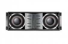
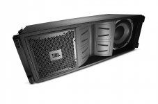
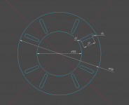
8CX300ND horn is unterminated, so sound waves will reflect off its edges back into the throat, interfering with the initial wavefront. Another part of the wavefront will detach and radiate at the edges, creating secondary sources. The simplest and most effective solution woul be to cover the exposed part of the woofer with a perforated disc, bridging horn surface to baffle and eliminating discontinuity. Angled slots with some melamine damping behind them may be better than simple round perforations, judging by JBL VT line array series.
See last drawing. You can easily prototype it with knife and stiff cardboard. Slot positions and dimensions are eyballed.
Attachments
Are you talking about improving this?8CX300ND horn is unterminated, so sound waves will reflect off its edges back into the throat, interfering with the initial wavefront. Another part of the wavefront will detach and radiate at the edges, creating secondary sources. The simplest and most effective solution woul be to cover the exposed part of the woofer with a perforated disc, bridging horn surface to baffle and eliminating discontinuity. Angled slots with some melamine damping behind them may be better than simple round perforations, judging by JBL VT line array series.
See last drawing. You can easily prototype it with knife and stiff cardboard. Slot positions and dimensions are eyballed.
I've just started building my first DIY home cinema speakers with this driver, I'll give your disc idea a try when I get as far as measurements.
"See last drawing. You can easily prototype it with knife and stiff cardboard. Slot positions and dimensions are eyballed"
Oh, it's so easy!😎
Oh, it's so easy!😎
Hi guys,this drivers is used in Dynamikks DB 8.2 speakers and I have this and this drivers sounds excelent in this horn enclosure with the right passive crossover.The bass gies down to 34hz -6dB and the detail from mid and high frequency ist just top notch.My good friend have Tannoy kensington with 8 inch tannoy coax and we made some sound test,and the beyma coax in dynamikks enclosure is so much better.I think the guys by dynamikks company from germany have done the best job with this drivers.
measure at different angles, 0-15-30°!but the tweeter is so so and doesn't seem it can get any better than this
- Home
- Loudspeakers
- Multi-Way
- Yet another Beyma 8CX300Nd/N bookshelf