I’ve been playing with a minidsp and a speaker I built and I’m confused as to what you use for say a midrange tweeter integration. I have a 33uf cap on the tweeter for protection so I don’t know if that naturally has a 6db roll off or not? So if I’m crossing at 1700hz to the midrange do I set the minidsp for 6db,12db,18,24db? Also the different types of filters Lynk,butterworth ect…
Do people normally set the crossovers on each driver at the same freq? As in midrange crossover 24db 1700hz and tweeter crossover at 24db 1700hz?
Or is there an underlap in the midrange as in setting it at 1500 24 while the tweeter is still at the 1700 24?
I know you want the meeting points to be 6 db down from each speaker so can that be an underlap in own another?
Thanks for the help.
You'll still find the same measurements and simulations are necessary with either kind of crossover. Didn't you find these same problems with passive crossovers?
Eli,
Have you checked out the minidsp setup(s) on YouTube?
There’s a lot on there, but check this one out:
How To Set Up MiniDSP 2x4 Active Crossover - YouTube
Secondly, you’re going to need a mic and a speaker measuring program.
Have you checked out the minidsp setup(s) on YouTube?
There’s a lot on there, but check this one out:
How To Set Up MiniDSP 2x4 Active Crossover - YouTube
Secondly, you’re going to need a mic and a speaker measuring program.
A 33uF capacitor doesn't give you much protection.....with a normal tweeter. Against steady-state DC, yes, but the long time-constant might still allow some problematic situations.
If you feel you need a series capacitor, best to size it down so that it exactly coincides with your crossover frequency and forms one of the "orders"..
Dave.
If you feel you need a series capacitor, best to size it down so that it exactly coincides with your crossover frequency and forms one of the "orders"..
Dave.
I'd take the cap out of the circuit ... design a suitable crossover w/your minidsp and then work out a fail safe circuit if so desired. Working out an active dsp crossover solution can be problematic with additional components in the path at or near said crossover point.
"an active dsp crossover solution can be problematic with additional components in the path at or near said crossover point."
Yes, it can be problematic but it can be beneficial either. You just need to make the passive filtering a part of the total filtering. That's all.
For example: place a capacitor in the signal path of a tweeter, adjust the tweeter's acoustical response to your target with the capacitor in place, done.
Last edited:
Except for the phase shift caused by the dsp filter.
Example: 4th order LR response. Tweeter has a cap providing 1st order acoustic slope. What do you choose in the dsp to obtain an acoustic 4th order response? ... a 3rd order Bessel? OK, but now what is the phase of the tweeter induced by the dsp w/a 3rd order Bessel filter? It's not going to be comparable to a phase shift induced w/4th order filter within the dsp unit. Now you will have to work around that issue to line up phase .. if you can 😉
Example: 4th order LR response. Tweeter has a cap providing 1st order acoustic slope. What do you choose in the dsp to obtain an acoustic 4th order response? ... a 3rd order Bessel? OK, but now what is the phase of the tweeter induced by the dsp w/a 3rd order Bessel filter? It's not going to be comparable to a phase shift induced w/4th order filter within the dsp unit. Now you will have to work around that issue to line up phase .. if you can 😉
Puppet, you need to read carefully what I wrote. It doesn't matter what filters you use in the DSP to achieve the acoustical target response with capacitor or no capacitor.
However, if you want to use a cap for any reason, you need to shape the driver’s acoustic response when the cap is in place. If you reaches the target response (e.g., LR4 2kHz high-pass), if the cap is in place, plus (any) DSP filters, the acoustic amplitude and phase response will be the same as that achieved without the cap, because they are the same acoustical LR4 2kHz high-pass response but one with a cap and one without the cap.
Of course they need different DSP filtering to achieve the same acoustical LR4 2kHz high-pass response.
Of course they need different DSP filtering to achieve the same acoustical LR4 2kHz high-pass response.
Last edited:
Take a driver and input a LR 4th order dsp filter (let's assume 4th order acoustic response) ... note the phase. Now, change that filter to a 3rd order Bessel dsp filter with a component that stimulates a 1st order roll off (again, assume a net 4th order acoustic response) ... note the phase.
The individual responses match ... but the phase won't match.
So, if the OP wants to crossover a mid and tweeter w/minidsp, the mixing and matching crossover types alters the phase in DSP and can present an issue at the crossover frequency eg. lobing errors and holes in the response on and off axis.
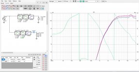
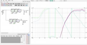
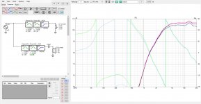
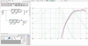
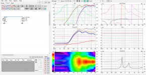
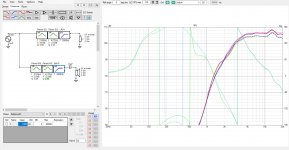
FYI quickie on VituixCAD. This is compression driver in a waveguide. There is two PEQ filters and a high pass filter to make close LR4 acoustic slope at 3000Hz. This is made as overlay visible on all the attachments as light blue phase trace and purple axial response.
On the crossover window the filters and driver is just copied for another branch, could have done all of this with one driver and set of filters, don't get confused 😀 The upper branch was used to generate the overlay and is muted on the attachments so it doesn't have any effect.
Attachments roll down from huge cap to a small cap, in addition to the DSP tweaked acoustic LR4 high pass. Just for fun to see how the phase and highpass response changes compared to no capacitor version of the same DSP filters.
1. huge cap around 6000uF, no meaningful effect
2. still huge 1000uF
3. 100uF
4. 10uF
5. Raw driver response, impedance also showing.
As you see the response doesn't change much until the smallest 10uF cap. Also the phase doesn't change too much, it is related to the frequency response. Notice how the frequency response and phase differs around ~2kHz where there is peak in the driver impedance. The cap interacts with the driver and additional DSP filters or passive parts would be required to tame that! Other than that using relatively large cap it doesn't affect much to the slope or phase. There is about 30 degrees and 2db difference at 3kHz in this case with the 10uF cap.
To negate the influence of the cap on the acoustic slope and match it back to LR4 it is just matter of changing the DSP high pass filter to 3rd order Butterworth, which I think you ment Puppet? 3rd order Bessel filter attached as well, can't get the response match with that. Filter frequency in both cases is tweaked so that phases match around 3kHz. Attachments 6 and 7.
Note the phases match nicely for the crossover region and up except where the driver impedance peaks are and also the frequency response differs there. Phase and frequency response are related and there shouldn't be any difference in phase if the frequency response was tweaked to be the same with or without the capacitor. These graphs are showing effects of the various filters to the measured acoustic output, which we are tweaking after all.
All this doesn't really matter, the response is seen in the simulator and getting it to liking is just a matter of tweaking with passive parts or DSP filters and it really doesn't matter what filters and parts are required as long as the response all around looks nice (and hopefully sounds nice 😀). Even if the phase differed for some reason it wouldn't matter either since it is just few more tweaks in the simulator. It is the acoustic output that matters eventually, not how to reach it.
Attachments

Last edited:
You sound like you've never done this before????Take a driver and input a LR 4th order dsp filter (let's assume 4th order acoustic response) ... note the phase. Now, change that filter to a 3rd order Bessel dsp filter with a component that stimulates a 1st order roll off (again, assume a net 4th order acoustic response) ... note the phase.
The individual responses match ... but the phase won't match.
So, if the OP wants to crossover a mid and tweeter w/minidsp, the mixing and matching crossover types alters the phase in DSP and can present an issue at the crossover frequency eg. lobing errors and holes in the response on and off axis.
I suggest to revisit your understanding of this and actually implement a real-world hybrid crossover using a passive component in conjunction with a line-level (active or DSP) to construct a proper acoustic filter.
This is very straightforward stuff and you've had a few excellent posts here already regarding the implementation......which you don't seem to believe. 🙂
Dave.
Last edited:
A 33uF capacitor doesn't give you much protection.....with a normal tweeter. Against steady-state DC, yes, but the long time-constant might still allow some problematic situations.
If you feel you need a series capacitor, best to size it down so that it exactly coincides with your crossover frequency and forms one of the "orders"..
Dave.
It’s the peerless corundum 1”. 633fz freq 8ohm. Still think it’s bad to
Have for protection? I’m crossing the tweeter at 1700.
Peerless DA25TX00-08 1" Corundum Dome Tweeter
Eli,
Have you checked out the minidsp setup(s) on YouTube?
There’s a lot on there, but check this one out:
How To Set Up MiniDSP 2x4 Active Crossover - YouTube
Secondly, you’re going to need a mic and a speaker measuring program.
Haven’t seen that video. Been trying to find some
Good videos on it for a while now.
I have a umik1 and a boom stand. REW is what I use for software but open to try a different program.
"an active dsp crossover solution can be problematic with additional components in the path at or near said crossover point."
Yes, it can be problematic but it can be beneficial either. You just need to make the passive filtering a part of the total filtering. That's all.
For example: place a capacitor in the signal path of a tweeter, adjust the tweeter's acoustical response to your target with the capacitor in place, done.
I’ve read that for protection on the tweeter you want a capacitors one octave away from your actual crossover point. Crossover point is 15-1700. 33uf cap. On a 633fs tweeter. 8ohm.
Except for the phase shift caused by the dsp filter.
Example: 4th order LR response. Tweeter has a cap providing 1st order acoustic slope. What do you choose in the dsp to obtain an acoustic 4th order response? ... a 3rd order Bessel? OK, but now what is the phase of the tweeter induced by the dsp w/a 3rd order Bessel filter? It's not going to be comparable to a phase shift induced w/4th order filter within the dsp unit. Now you will have to work around that issue to line up phase .. if you can 😉
Can always adjust delay to have it match with the mid at the crossover point?
Also, the tweeter is in a wave guide. Driver alignment is very close to each other.
I’ve read that for protection on the tweeter you want a capacitors one octave away from your actual crossover point. Crossover point is 15-1700. 33uf cap. On a 633fs tweeter. 8ohm.
You don't need to use a big capacitor like that if you make the capacitor a part of the total filtering as tmuikku demonstrated in post #12.
DSP will get same response as passive crossovers. IF passive needs overlap/underlap then dsp would need that too. Another way to add cap to tweeter is like this: assume that intended target is 2nd order crossover then 1st order can be from cap and another 1st order from dsp. Same can be done for 24db xover tooI’ve been playing with a minidsp and a speaker I built and I’m confused as to what you use for say a midrange tweeter integration. I have a 33uf cap on the tweeter for protection so I don’t know if that naturally has a 6db roll off or not? So if I’m crossing at 1700hz to the midrange do I set the minidsp for 6db,12db,18,24db? Also the different types of filters Lynk,butterworth ect…
Do people normally set the crossovers on each driver at the same freq? As in midrange crossover 24db 1700hz and tweeter crossover at 24db 1700hz?
Or is there an underlap in the midrange as in setting it at 1500 24 while the tweeter is still at the 1700 24?
I know you want the meeting points to be 6 db down from each speaker so can that be an underlap in own another?
Thanks for the help.
DSP will get same response as passive crossovers. IF passive needs overlap/underlap then dsp would need that too. Another way to add cap to tweeter is like this: assume that intended target is 2nd order crossover then 1st order can be from cap and another 1st order from dsp. Same can be done for 24db xover too
I understand that. I just don’t know if a 33uf cap makes it into a 6db slope. I really just have the cap for some sort of protection in case the dsp doesn’t work or amp pop when turning on. But my amps don’t have issues. It’s mostly just for some sort of protection.
I was more curious as to setting the crossover in the dsp if they should be set at the same frequency or one higher or lower than the other. Like 1700 tweeter. 1500 mid
- Home
- Loudspeakers
- Multi-Way
- Curious about dsp crossovers/overlap?