Hi everyone,
recently one of my Neumann KH120A studio monitors has failed.
The power supply had a fault right after powering up, and blew the mains fuse. It did not trip the breaker. Since then it just keeps blowing the fuse.
I have opened up the monitor and inspected the circuit board. I tested a few components on the primary side of the psu: bridge rectifier, ntc, filter capacitors and inductors, primary side of the transformer. These all seem to be ok.
The switching mosfet has been removed and tested and it's shorted.
I have ordered some spares. And I also ordered a replacement switching controller IC.
I am not very experienced with smps repair, I have been looking at a ton of youtube videos and tutorials trying to learn a bit.
At the moment my concern is that just replacing the mosfet maybe not enough as there is potentially something else shorting it out.
Can you recommend any further testing to be done or components to replace before powering up again ?
Unfortunately the manufacturer doesn't provide schematics and the pcb is multi-layer so not very easy to trace.
The only good thing is that the second monitor I have is working well so potentially I could open that up and make comparisons.
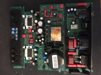
I have attached a photo of the board
recently one of my Neumann KH120A studio monitors has failed.
The power supply had a fault right after powering up, and blew the mains fuse. It did not trip the breaker. Since then it just keeps blowing the fuse.
I have opened up the monitor and inspected the circuit board. I tested a few components on the primary side of the psu: bridge rectifier, ntc, filter capacitors and inductors, primary side of the transformer. These all seem to be ok.
The switching mosfet has been removed and tested and it's shorted.
I have ordered some spares. And I also ordered a replacement switching controller IC.
I am not very experienced with smps repair, I have been looking at a ton of youtube videos and tutorials trying to learn a bit.
At the moment my concern is that just replacing the mosfet maybe not enough as there is potentially something else shorting it out.
Can you recommend any further testing to be done or components to replace before powering up again ?
Unfortunately the manufacturer doesn't provide schematics and the pcb is multi-layer so not very easy to trace.
The only good thing is that the second monitor I have is working well so potentially I could open that up and make comparisons.
I have attached a photo of the board
Attachments
I have limited experience with SMPS repair too, so if I were you I would probably throw in one Mosfet without further testing and if that blows again, only then I would try to figure out drive voltage of the mosfet etc...
Hopefully you didn't order only one? 😉
Hopefully you didn't order only one? 😉
I have a few spare mosfets on delivery. Went ahead and removed the controller ic and ordered spares of that too.
Also took out two optocouplers and tested out of circuit, they work fine.
I have checked all components in the primary side for shorts and everything seems ok.
My plan is to fit a new mosfet and controller ic and power up with a variac and a lightbulb limiter. I hope the lightbulb limiter will prevent any further damage in case there is still a short somewhere.
I am trying to figure out how to test the transformer, is there a way to measure it in circuit and understand if there are shorted turns somewhere ?
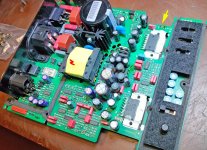
It's highly likely that the transformer is intact, as it's considered more reliable than most (electrical) parts you would find within an SMPS. However, things also depend on the circuit topology which, I guess in this case (from the photograph), is a flyback converter.
just tried the new ic controller and mosfet. at power up the mains fuse doesn't blow anymore so I guess that means there aren't anymore shorts on the primary side.
now the power supply is basically failing to start up. the large reservoir capacitor is charging very slowly and there are no output voltages. the ac voltage on the input of the rectifier is also raising slowly from 0 to a few volts.
I am guessing the problem could be a short on the secondary side and as a consequence of that there is no voltage feedback to the controller ic ?
I have read about a method to disconnect the optocoupler and replace it with a diode so the output voltage goes at maximum and any shorted component on the secondary side will heat up. but I don't think in this case it's safe since the amp circuitry cannot be isolated from the psu output and the increased output voltage could damage the amp components...
do you have any suggestions on how to proceed with the troubleshooting ?
Last edited:
the ac voltage on the input of the rectifier is also raising slowly from 0 to a few volts.
You're supposed to read 230V at the rectifier input, bypass the EMI filter and check again.
This supply doesn't have active PFC, does it? Usually the reservoir cap in a traditional SMPS should be charged nearly instantly, as the circuitry tends to be line --> fuse -> EMI suppression --> rectifier --> cap with little else in the way. (How quickly does it discharge when power is turned off?) Maybe the ohmmeter will find a surprise on the way.
You can try to ohm out the secondary side to check for blatant shorts on the rails. Unhappy shorted SMPS' tend to exhibit very typical pulsing output though, as voltage ramps up until over-current protection kicks in, the output shuts off and the cycle repeats.
Speaking of shorts, there should normally be some secondary-side (fast) rectifier diodes that would be worth checking... could be in a TO-220ish package, like what's seen to the left of the perforated section.
Where did you source your replacement parts? There is no shortage of shady dealers on eBay or Aliexpress with potential fakes.
Finally, we are talking legit pro audio gear here, and standards for customer service tend to be fairly high in this area. If you are truly stuck, I would suggest contacting Neumann / Sennheiser customer service and see whether they can't throw you a bone. I assume they designed the entire amplifier / PSU board in-house, and it's still a current model, so chances of support being able to get ahold of someone who knows something aren't too slim.
apologies for the confusion there was a poor connection on the bridge rectifier input.
now the bulk capacitor is charging, with a 115V ac input i have a varying voltage between 154V - 158V dc on the capacitor. I have not tried to raise to input voltage to 240v.
there is a whining pulse noise coming from the board with a period of about 1 second, if the drivers are connected that noise leaks out of the speaker
looks like the psu is failing to start
there are 4 output voltage test points marked +UB, -UB, +15V and -15V
+UB is stuck at 0 , +15V is fluctuating between 0 and -0.3v and the -15V and -UB are fluctuation between 0 and -1.3V
Last edited:
The minimum voltage for 240V equipment should be around 180V-200V. Have you checked the amplifiers ?
on the rear panel it says the input of the device can be anywhere between 100V and 240V AC. I think it's an universal input power supply
I thought powering up with a lower voltage could perhaps be safer.
Found a shorted rectifier diode on the transformer secondary, replaced that and the short between +UB and 0V is gone
the voltages on the output are still fluctuating but the +/- 15V are now roughly +/- 5V and the +/- UB is about +/- 2V
The pulsating whining noise has reduced to a very faint ticking sound
There is a pair of regulators, I think they maybe are a 7915 and 7815. Would it be a good idea to remove them and inject +/- 15V with a bench power supply ? Maybe I can figure out if there is a short on the +/- 15V rails
read on a blog that the +/- UB rails are 42V
these voltages are only used by the two amplifier ic tda7293
since the shorted diode was on the +UB rails could it be the tda7293 are damaged ?
i measure 280ohm resistance between +UB and -UB
is there a way to test the tda7293 in circuit ?
these voltages are only used by the two amplifier ic tda7293
since the shorted diode was on the +UB rails could it be the tda7293 are damaged ?
i measure 280ohm resistance between +UB and -UB
is there a way to test the tda7293 in circuit ?
Last edited:
removed the tda7293 ics and the voltages are still fluctuating but closer to the correct values.
UB rails are now fluctuating between +/- 39V and up to the full +/- 42V
15V rails are spiking from 0V to the full +/- 15V
the section labeled +5V has now a steady +4.8V
the relay in the input section is clicking with a frequency of about 1s, that is in sync with the 15V rails going from 0V to full voltage
I am not quite sure why the psu rails are still pulsating but maybe they need the amplifier ics to be in circuit in order for the psu to function ?
I am gonna order a couple of spare tda7293 and see if once the ics are back in circuit the supply remains stable
..read on a blog that the +/- UB rails are 42V...
You could have simply opened up the working unit you mentioned in the opening post and made comparisons..
is there a way to test the tda7293 in circuit ?
You could try supplying +/-42V from an external source, bypassing the PSU altogether.
...the relay in the input section is clicking with a frequency of about 1s, that is in sync with the 15V rails going from 0V to full voltage...
I guess that relay is meant to bypass a resistor during starup, so as to limit the inrush current into the unit. Some kind of shut-down / protection due to a fault on the secondary side could be the reason behind the continued restart attempts.
good news today I have fitted new ics in the amplifier and the monitor speaker is now fully working !
the voltages seems fine, the +UB/-UB is actually around 35V under load.
I have been running the speaker for about an hour and all is well, fingers crossed !
to make it useful to someone who might end up in the same situation this is the list of faults I had :
- open mains fuse
- shorted switching mosfet
- dead switching controller ic (not confirmed but very likely)
- shorted rectifier diode on transformer secondary
- defective amplifier ic (i think it was the one for the tweeter but I ended up replacing both)
I am very glad I managed to fix it instead of paying over £240 for the service center flat rate... and it's also one less piece of electronics that goes to the landfill, since they don't do component level repairs but replace the entire board !
Do enquire if there're other units out there that have possibly failed in a similar way, as you could make some money out of repairing these for people... I think you've posted this before:
Converting active monitors to passive
Converting active monitors to passive
Last edited:

- Home
- Amplifiers
- Power Supplies
- Neumann KH120A studio monitors SMPS repair