Just want to make sure I don’t blow out a transformer winding so please allow me to run this by you to make sure. I’ll be using a Hammond 378X power transformer for my KT88 tube amplifier and I have a question about the filament windings.
The amplifier uses two KT88 tubes for the output which I’ll supply AC heater current to using the 6.3V CT 6A filament winding, with the CT hooked to chassis/GND.
The small signal tubes I’d like to supply DC heater current to, by full bridge rectifying the 5V CT 3A filament winding as obviously 5x1.41=7V, which with either a diode drop or a series resistor gets us right at 6.3V.
The question is regarding the connection to chassis/GND. Can I connect the CT on the 5V CT 3A winding to chassis/GND or is it better to leave CT floating and connect either end of the rectified DC voltage to chassis/GND whichever gets the least amount of hum?
Hammond 378X transformer
378X - Hammond Mfg.
Looking forward to your replies, thanks!
Attachments

If no other node in the filament circuit is connected elsewhere, you can connect the CT
to ground, or elevate it to some DC voltage within the VA tube's H-K rating.
Or instead of the CT, you can connect one end of the filament to ground, or to
an elevated DC voltage (a decoupled resistor voltage divider).
With a FWB rectifier, the CT does not have to be connected to anything.
to ground, or elevate it to some DC voltage within the VA tube's H-K rating.
Or instead of the CT, you can connect one end of the filament to ground, or to
an elevated DC voltage (a decoupled resistor voltage divider).
With a FWB rectifier, the CT does not have to be connected to anything.
Last edited:
I think that 7Vdc after recticfication of 5Vac is too optimistic. The multiplier "1.41" will be lower in practice because of the voltage drop in the diodes of the bridge retifier (the current passes two diodes at any time) and the resistance in the 5 V winding. I would atleast try it out before you decide to do it like this. And use a bridge rectifier with the lowest voltage drop you can find.
I doubt if 0.9 is true. I have so many practical examples that contradict this. For instance: From 230 Vac you get about 300 to 310 Vdc with a bridge rectifier under load, so the multiplier is a bit more than 1.3 in that case.
From 6.3 Vac windings I always succeeded to get 6.3 Vdc. In only one case I couldn't use an extra RC after the C at the bridge rectifier to further smoothen the rectified current. In all other cases there was some extra voltage left to do this.
The lower the Vac is, the more the voltage drop in the bridge rectifier 'spoils the party'.
Last edited:
Yes, this is for low voltage. The OP is trying to get 6.3DC, high current, from 5V AC. That's a bit of a stretch.
I'm aware that things are different for high voltage, I get 400VDC from a 600Vct secondary, under 200mA load.
I'm aware that things are different for high voltage, I get 400VDC from a 600Vct secondary, under 200mA load.
You will be fine with a doubler, using the right capacitors. You could even find an LDO regulator to set exactly the output voltage to 6.3V.I was thinking of this instead of the full bridge as there's enough current capacity. This allows me to drop any excess voltage with resistors, it is probably best to do a RC after the main caps so I get some extra smoothing as a bonus.
You will be fine with a doubler, using the right capacitors. You could even find an LDO regulator to set exactly the output voltage to 6.3V.
Yes, but I have a strict 'as few as possible semis' policy 😀
You already have two rectifiers in series, the bridge ones, you will not even reach 6.3V DC, even less have "extra"full bridge rectifying the 5V CT 3A filament winding as obviously 5x1.41=7V, which with either a diode drop or a series resistor gets us right at 6.3V
Not with filament load.
You CAN ground CT if no other option but "normal" is to ground rectified negative.The question is regarding the connection to chassis/GND. Can I connect the CT on the 5V CT 3A winding to chassis/GND or is it better to leave CT floating and connect either end of the rectified DC voltage to chassis/GND whichever gets the least amount of hum?
If anything, you now have a slightly above 5V DC rail available, which can be used to drive a relay coil,some delay timer, etc.
Even if not interested now, "it´s there" anyway and costs nothing.
Hey, it might at least power a front panel LED 🙂
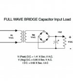
That guide is not fully WRONG but poorly written, they are mixing DC and AC ideas.
* WITH a significant capacitor there, Peak voltage applies.
* WITHOUT a capacitor and a fully resistive load, Average voltage applies, if somebody is interested in that for Academic purposes (as in what will a DC ammeter show) but for hot filaments, RMS voltage is the key, because it shows "heating power" capacity.
* IDC shows a derating factor.
Physics rules always apply, it´s just that for a 400VDC supply diode drop can be ignored, not so with a 5-6VDC one.I'm aware that things are different for high voltage, I get 400VDC from a 600Vct secondary, under 200mA load.
But the diode drop is always there, even in the HV one.
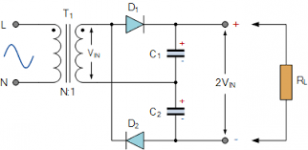
(Shows a half wave voltage doubler)I was thinking of this instead of the full bridge as there's enough current capacity.
Maybe but be aware you will have a GROSS drop in current capability,should do the Math but it´s about 40% or so remaining.
So if you have "generous" 50% or even 100% nominal AC current capability, it will not be enough, go figure.
HV windings expect capacitive input, so that is given consideration by winders, filament ones in principle expect only resistive load, so are specc´d tightly.
@JMFahey,
All very valid points, thank you!
I indeed didn't factor in the diode losses, which even for a Schottky diode full wave bridge would mean that when loaded the net voltage would never be able to reach 6.3V. The half wave voltage doubler gets around that issue and given the fact that I have a 5V/3A CT winding available and only need to supply heater current for two small signal tubes for a total of <1A this could be just the ticket.
But I'll make sure to try this on the bench first, just to make sure.
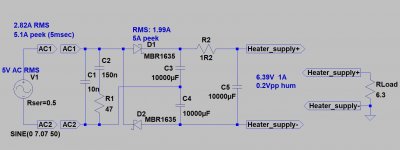
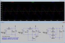
Thanks euro21, I was just doing the same thing, see attached. There's a fair bit of ripple indeed, the voltage doubler looks okay though. I modelled using the actual 378X transformer specifications as found on the Hammond website.
Hammond 378X transformer
https://www.hammfg.com/files/parts/pdf/378X.pdf
Hammond 378X transformer
https://www.hammfg.com/files/parts/pdf/378X.pdf
Attachments
I was thinking of this instead of the full bridge as there's enough current capacity. This allows me to drop any excess voltage with resistors, it is probably best to do a RC after the main caps so I get some extra smoothing as a bonus.
Best idea sofar in this thread but drop the excess with a 3-terminal regulator & apply real DC to your heaters.🙂
Best idea sofar in this thread but drop the excess with a 3-terminal regulator & apply real DC to your heaters.🙂
You heretic! I want to use as little semiconductors as possible, a few transistors are okay, but an IC, that's just admitting you failed to implement a working solution with simpler means from a more civilized age! 😀
With a doubler you can get about 1A DC from a 3A winding. Your caps must have at least 1A ripple current rating - more is better.
The working solution is getting a secondary with the proper voltage and current, but YOU are not implementing it!!!you failed to implement a working solution with simpler means from a more civilized age!
😉
The working solution is getting a secondary with the proper voltage and current, but YOU are not implementing it!!!
😉
Well, since you brought it up. I can’t for the life of me figure out why Hammond doesn’t just offer a winding on their PTs that is ideally suited for full wave bridge rectification and able to provide heater current for 3-4 small signal tubes, seems like a no-brainer to me? They could just add some extra windings to the existing 6.3V CT, make a 8V CT winding with 6.3V taps for example, so you have the option to do that, those few meters of copper wire would be well worth the cost.
Coming up with a 'suits all' solution quickly puts one out of the market. Not everyone drives a RR, Fords & Chevies are a lot less money. And still get us there, for the most part on time!
- Home
- Amplifiers
- Tubes / Valves
- Hammond PT 5V CT winding hookup?