Hi All,
I am just about to assemble my first tube amplifier and have designed what I think is a workable SE UL circuit, of course subject to minor tweaking once built.
I already have most of the parts listed, but wanted to run it by everyone before I start drilling holes and cutting transformer leads.
I have used a mosfet follower as it allows me to use one hammond power transformer with no requirement for elevated heater supplies.
Please critique at will, I am particualy interested to know about the power suppy design - working with tube rectifiers is new to me, I believe I am right on the edge of the 5AR4's capability.
The amp will initially be run with EL34's but I may change the cathode resistor and run KT88's at some point. I realise the power supply input cap and resistor may need some tweaking to provide the correct anode voltage.
Proposed key components as follows:
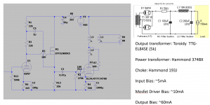
Power transformer: Hammond 374BX, 750V CT:
https://www.hammfg.com/files/parts/pdf/374BX.pdf
Power supply capacitors,would love advice on these as I don't have much safety margin: 500V Rubycon LXW series:
https://au.mouser.com/datasheet/2/977/e_LXW-1600626.pdf
Choke: Hammond 193J (10H, 200mA):
https://www.hammfg.com/files/parts/pdf/193J.pdf
Output Transformer: 5K Toroidy TTG-EL84SE:
TTG-EL84SE - Tube output UL transformer [5kOhm] EL84 / 6V6 SE - Shop Toroidy.pl
Any advice is appreciated!
Greg
I am just about to assemble my first tube amplifier and have designed what I think is a workable SE UL circuit, of course subject to minor tweaking once built.
I already have most of the parts listed, but wanted to run it by everyone before I start drilling holes and cutting transformer leads.
I have used a mosfet follower as it allows me to use one hammond power transformer with no requirement for elevated heater supplies.
Please critique at will, I am particualy interested to know about the power suppy design - working with tube rectifiers is new to me, I believe I am right on the edge of the 5AR4's capability.
The amp will initially be run with EL34's but I may change the cathode resistor and run KT88's at some point. I realise the power supply input cap and resistor may need some tweaking to provide the correct anode voltage.
Proposed key components as follows:
Power transformer: Hammond 374BX, 750V CT:
https://www.hammfg.com/files/parts/pdf/374BX.pdf
Power supply capacitors,would love advice on these as I don't have much safety margin: 500V Rubycon LXW series:
https://au.mouser.com/datasheet/2/977/e_LXW-1600626.pdf
Choke: Hammond 193J (10H, 200mA):
https://www.hammfg.com/files/parts/pdf/193J.pdf
Output Transformer: 5K Toroidy TTG-EL84SE:
TTG-EL84SE - Tube output UL transformer [5kOhm] EL84 / 6V6 SE - Shop Toroidy.pl
Any advice is appreciated!
Greg
Attachments
Last edited:
About the 5AR4: I think the value of C1 is a bit too high. The datasheet gives 60 uF as the maximum value. In your schematic there is R1 of 50 Ohm preceeding C1 which will protect the 5AR4 a bit but if I were you, I would lower the value of C1 to 60 uF.
For the rest I don't see why the 5AR4 would be running at its edge. The current consumption of your amplifier (both channels) is about 150 mA while the maximum current of the 5AR4 at the voltage of your power transformer is 250 mA.
For the rest I don't see why the 5AR4 would be running at its edge. The current consumption of your amplifier (both channels) is about 150 mA while the maximum current of the 5AR4 at the voltage of your power transformer is 250 mA.
Last edited:
If you drop it to 50uF, you can get rid of that 50R unless you need a voltage drop and the waste heat that comes with it.
Thanks Kodabmx, I'll see how I go. My PSUD simulation suggests I need the 50R, but I'll get rid of it if I don't end up needing it.
You probably need the 50 ohms with the bigger cap but not with a little one. It will come down with a smaller cap (which is why you measure less power from your amp when the electrolytics start going bad). If your voltage is still too high with 50uF, keep dropping the cap value. Increasing the ripple at the first stage drops the average voltage, and the LC second section cleans that up. If you end up with a small enough cap (10 to 20 uF) you can use a *good* one that will never go bad on you.
Thanks wg_ski, will do.
Does anyone have any thoughts on the capacitors I have chosen - the Rubycon ones? Or any of the circuit design in general? Going to put drill to steel next weekend all going well.
Does anyone have any thoughts on the capacitors I have chosen - the Rubycon ones? Or any of the circuit design in general? Going to put drill to steel next weekend all going well.
Those look like good caps, but you are going to be running them right up against limits. I might be inclined to use two in series for the first section. It’s going to charge to the peak voltage, less 60 or so volts in the rectifier.
I agree on ditching the R1 50ohm and lowering that first cap to a 22-33uf (solen 630V film cap). I've built a bunch of PS like that with a 10H choke followed by a 450-500V 200-250uf and had no issues, just avoid those JJ 5AR4, they can't handle that voltage.
Higher voltage caps are now readily obtainable, so IMHO the series caps are out. I agree with Stephe’s suggestion of a film cap for C1 if you want it to last (and sound good). What she suggested, or something like this (other values available too):
https://www.mouser.com/ProductDetail/Panasonic/EZP-V60506MTS?qs=OlC7AqGiEDlYqiP366v3oA==
Or if you want to stick to ‘lytics see this:
https://www.mouser.com/ProductDetail/EPCOS-TDK/B43544B7476M000?qs=GG15fDrrStouL5Uyu9CGtg==
https://www.mouser.com/ProductDetail/Panasonic/EZP-V60506MTS?qs=OlC7AqGiEDlYqiP366v3oA==
Or if you want to stick to ‘lytics see this:
https://www.mouser.com/ProductDetail/EPCOS-TDK/B43544B7476M000?qs=GG15fDrrStouL5Uyu9CGtg==
If you end up with a small enough cap (10 to 20 uF) you can use a *good* one that will never go bad on you.
= MKP cap, so it will never go bad and you don’t need to find 500+ volt electros. Even 550 is iffy here. If I were being a cheapskate I’d use two 400V in series because I have some and it provides margin, but you can get 630V in film caps. 20 some odd uF isn’t crazy expensive.
And those reissue vacuum rectifiers like to arc over. Fine at 200 volts, maybe 300 in some little bitty EL84 amp, but at these voltages they misbehave. Not every time, but often enough to be a pain in the ***. One trick they like using these days is to put a UF4007 silicon diode in series with each half of the rectifier. They take the reverse voltage so the tube doesn’t try to block it, and you still get the proper dropping characteristic of the tube rectifier. Or find some good NOS rectifiers and not have to worry about it.
Definitely agree with the film cap recommendation and the 4007 diodes in series with the 5ar4, it’s a belt and suspenders thing. Use 630v to be safe on start up. The Solens recommended are the least expensive good option. I hope you get hooked on tubes, I did!
Thanks for the tips everyone, I'll make the relevant modifications. Glad the JJ 5AR4 was mentioned as that happens to be what I bought! I'll run the solid state diodes in series as suggested. How is everyone mounting the MKP film caps in a point to point wired amp? Perfboard maybe?
Any thoughts on the amp schematic itself?
Thanks again,
Greg
Any thoughts on the amp schematic itself?
Thanks again,
Greg
I use those 3m zip tie anchor squares. They are self adhesive and perfect to hold parts down. Just zip whatever through the mount and you’re set. Long parts get two. You can point to point easily.
Ok thanks, interesting! I have a hard time trusting adhesives, but i guess if you're going that route one could also try the "permanent" 3M double sided tape?
The ones that I got have bolt holes if you want to double secure. I’ve been using them in a KT120 SE amp for two years with no failures. They are the heavy duty permanent ones. You can trust them.
Actually I've seen both Panduit and 3M squares dry out, and so wouldn't rely on them
mechanically unless bolted down. You'd never find them unbolted in a commercial product (I hope).
And shipping G forces can detach them when holding a heavier part down.
mechanically unless bolted down. You'd never find them unbolted in a commercial product (I hope).
And shipping G forces can detach them when holding a heavier part down.
Last edited:
- Home
- Amplifiers
- Tubes / Valves
- Seeking Critique of first Tube Amp Design