I love tuners. I've got several of them, including receivers. This time I decided to recap my old Mission Tuner. It's been built in 1985, April 20th to be precise (thanks to Mission folks who identified this on the PCB). Why did I do that? Because it's 36 years old, and the blue Philips caps are not known to last forever. Also, I noticed that it's going wrong sometimes, not able to keep frequency or signal, whether cold or warm (alternatively). So I thought that I could see what's around and detect potential problems here at first.
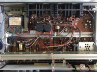
The PCB is quite simple to get out, I won't insist on this. Always take pictures before, and use some small paper sticks to remember where the wires go.
Taking the electrolytic caps apart and measuring them (twice on 2 different devices), ALL blue Philips were out of specs. Really out (like 2µF instead of 100, or ESR > 40ohm...). The only one that was good was a small yellow Nichicon (probably an old repair).
Good news, as it is a quite simple job to do. Hoping that it will be enough.
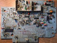
Having taken out all of them, I'm now able to make a comprehensive list (BOM) that I post as a picture down this page. in case it's useful for someone without unsolder them all before ordering. There could be some small differences if the model is different, of course, but I guess it should be near the values on this list. Of course, would anyone need the xls file, just ask.
I post a picture of the PCB once all electrolytic caps taken out, so one can see where they take place and which values they are. I wrote values on the picture at the exact place where you'll find the caps.
I'm waiting for 680µ/16V I had forgot to order on my first try 😕 to finish the work. While I'm waiting for the parts, I've decided to repair the small issues (broken plastic lugs as usual on the Mission apparels, cleaning and solder reflow where necessary, maybe a metal cover on top of the HF tuner section if I find some adequate piece of steel in my small recycle mess...).
I'll post pictures of the final condition if after all that, the tuner is OK.
Thanks for reading, I'm happy if it can help someone.
The PCB is quite simple to get out, I won't insist on this. Always take pictures before, and use some small paper sticks to remember where the wires go.
Taking the electrolytic caps apart and measuring them (twice on 2 different devices), ALL blue Philips were out of specs. Really out (like 2µF instead of 100, or ESR > 40ohm...). The only one that was good was a small yellow Nichicon (probably an old repair).
Good news, as it is a quite simple job to do. Hoping that it will be enough.
Having taken out all of them, I'm now able to make a comprehensive list (BOM) that I post as a picture down this page. in case it's useful for someone without unsolder them all before ordering. There could be some small differences if the model is different, of course, but I guess it should be near the values on this list. Of course, would anyone need the xls file, just ask.
I post a picture of the PCB once all electrolytic caps taken out, so one can see where they take place and which values they are. I wrote values on the picture at the exact place where you'll find the caps.
I'm waiting for 680µ/16V I had forgot to order on my first try 😕 to finish the work. While I'm waiting for the parts, I've decided to repair the small issues (broken plastic lugs as usual on the Mission apparels, cleaning and solder reflow where necessary, maybe a metal cover on top of the HF tuner section if I find some adequate piece of steel in my small recycle mess...).
I'll post pictures of the final condition if after all that, the tuner is OK.
Thanks for reading, I'm happy if it can help someone.
Attachments
Don't make any changes in the RF sections, including the shielding. That will detune (or worse) the circuits.
OK rayma, I won't touch this section. I agree that Mission engineers probably know what they are doing (better than me!) even if I was sceptical about the shielding. I just repaired a Tandberg TR2045 which got a shielding as often seen. I just thought about trying but after reading your words, it's probably a wrong idea.
I also have a few Cyrus One / Two amplifiers and PSX at home, and repaired or rehabbed them. I then noticed how they are remarkably well built. So I'll leave it as it is, just change what's necessary.
😉
I also have a few Cyrus One / Two amplifiers and PSX at home, and repaired or rehabbed them. I then noticed how they are remarkably well built. So I'll leave it as it is, just change what's necessary.
😉
Don't ask how i know about that.
The cost of a "lid" on the shields is tiny, and there's a good reason it's not there.
The cost of a "lid" on the shields is tiny, and there's a good reason it's not there.
😉
Absolutely right. Nearly no cost, so there is a good reason. But which?
In any case, this "cheap" tuner sounds right.
Absolutely right. Nearly no cost, so there is a good reason. But which?
In any case, this "cheap" tuner sounds right.
OK. Does this means that the adjustments have been made according to that "free air" RF section?
When you write "add parasitics", tell me, it's not the case with all lids in that situation? But I agree that it's been drawn this way for good reason, and it has probably been listened to for many hours. Anyway I never heard interferences while listening to it, which confirms its fine conception.
When you write "add parasitics", tell me, it's not the case with all lids in that situation? But I agree that it's been drawn this way for good reason, and it has probably been listened to for many hours. Anyway I never heard interferences while listening to it, which confirms its fine conception.
There are some "roofed" shields with holes for access to the internal adjustments,
if that is how it was designed.
if that is how it was designed.
Just wanted to say that the Tuner once recapped is working perfectly (as it should at least). I forgot to take pictures of the circuit after that, was too much in a hurry to have a listening session... I'll do that in that thread, hope soon. Thanks to all advices and care.
Well done Perelman!
I own the same tuner (Issue 6, the first plastic case version), it works perfectly for half an hour, then the left channel stops suddenly working. I suspect that some caps could be defective, but to have a better idea I'm looking for the service manual, or at least for the schematics.
Where could I catch it?
Thx a lot in advance to everyone
Maybe here? It doesn't specify 6, but indicates the model produced between 1985 and 1992, with a manual for both a Mk 1 and a Mk 2 version.
https://www.hifiengine.com/manual_library/cyrus/tuner.shtml
https://www.hifiengine.com/manual_library/cyrus/tuner.shtml
- Home
- Source & Line
- Analogue Source
- Mission Cyrus Tuner recapping