I want to see the distortion on the output of the amp, both channels displayed at the same time.
Images with no load, stereo loading and bridged loading would be useful.
Images with no load, stereo loading and bridged loading would be useful.
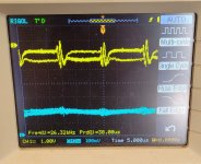
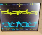
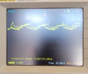
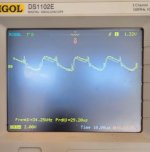
Set your scope:
2ms
5v/div
DC coupling
each trace aligned to the center of the display (vertically)
100Hz test tone
drive the amp with enough signal so that the output swings to about ±3/4 of the display.
2ms
5v/div
DC coupling
each trace aligned to the center of the display (vertically)
100Hz test tone
drive the amp with enough signal so that the output swings to about ±3/4 of the display.

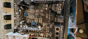
Are you sure that the 0.1 ohm source resistors are within tolerance?
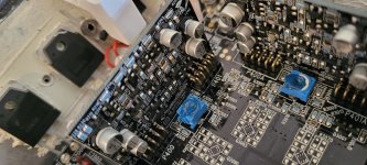
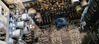
I'm not sure about this board but a board from a similar amp uses D204 and D205 on the driver boards in the over-current protection circuit. Lifting them will tell you whether the problem is in the protection circuit or in the drive circuit.
I'm not sure about this board but a board from a similar amp uses D204 and D205 on the driver boards in the over-current protection circuit. Lifting them will tell you whether the problem is in the protection circuit or in the drive circuit.
Is there a pin on the audio driver board header that is initially (on remote application) at 13v then after a few seconds, goes to about -7v?
- Home
- General Interest
- Car Audio
- Rockford t600-2 distortion