I’m starting a new thread on this amp so there is no confusion as to the problem .
The amp shorted the outputs and the power supply fets after rebuilding it .
The outputs shorted gate to drain .
I’m going to rebuild this amp again .
My question is I’ve heard a few different things about repairing this amp .
I don’t wanna say 1 person is right one person is wrong . Everyone that has helped me with this amp so far has given great advice .
Ok so here’s my question .
The output transistors shorted gate to drain I removed them and checked the gate resistors . Some read 32.9 ohms and others 32.8 ,32.6 ect .
Wondering when repairing these large amps like this should the gate resistors be all matching as far as value like getting all of them to read 32.9 for example or does it matter if 1 reads 32.9 the other reads 32.6 ?
I’m wondering if this causes issues in these large amps since first rebuild was unsuccessful.
Was there any leakage or a short between the drain and source for the FET(s) that shorted g-d?
The gate resistors will have a tolerance band. The value should be within that tolerance.
The gate resistors will have a tolerance band. The value should be within that tolerance.
The outputs that shorted gate to drain there is leakage between drain and source They measure 0.501K in both directions
Are you sure that there isn't an intermittent connection on one of the vias on the header or on the 12v regulator?
this uses irfp064n correct? Is the short only 1 way, Meaning red probe on gate, black probe on drain results short but black probe on gate, red probe on drain charges the caps(or visa versa)? If so, this is normal.
Did the fets blow right away after repair or after sometime with the customer?
Also make sure to check rectifiers, I keep hearing "they never blow" but myself and another hobbyist have had a fair share of bad rectifiers.
Did the fets blow right away after repair or after sometime with the customer?
Also make sure to check rectifiers, I keep hearing "they never blow" but myself and another hobbyist have had a fair share of bad rectifiers.
Last edited:
The outputs blew which shorted the power supply fets .
The outputs are shorted in both directions . Same with the power supply fets .
I repaired the amp as it’s my own amp and let it sit for awhile until I installed it and it blew .
So going through the entire amp to figure out why if the outputs I used weren’t right or something else caused this issue
The outputs are shorted in both directions . Same with the power supply fets .
I repaired the amp as it’s my own amp and let it sit for awhile until I installed it and it blew .
So going through the entire amp to figure out why if the outputs I used weren’t right or something else caused this issue
" if the outputs I used weren’t right"
I have this amp, if you have any questions on numbers let me know. Off the top of my head outputs were 360LC
I have this amp, if you have any questions on numbers let me know. Off the top of my head outputs were 360LC
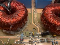
I’m still in the process of rebuilding this amp top to bottom . I’m almost done with the power supply section of the amp .
When I got this amp it had IRFP360LC’S for the outputs .
Now that I’m increasing the input voltage to 16 volts instead of 14.4 wondering if these outputs will survive .
I have a variable power supply that I can use at 16 volts to power up the power supply board in the amp but the power supply is only good for 10 amps .
wondering if I can use this supply to get an accurate reading on what the rail voltage is when powering up the amp ?
And do I measure the rail voltage at start up or when the amp is idling to see if I need to use different outputs in the amp
The rail voltage should be measured at idle when the supply voltage is as high as you expect it to be.
Isn't the Z2HV already a high voltage amp without mods.
Isn't the Z2HV already a high voltage amp without mods.
It’s supposed to be a high voltage amp without any mods . I rebuilt the amp once and it played perfectly fine for hours on the bench at 14.4 volts . I tested it up to clipping . I then installed it in the vehicle and supplied the amp with 16 volts and as soon as I turned the head unit on to supply the remote voltage to amp the amp protected and a split second later the outputs shorted in all 4 banks and blew the power supply fets. So I was wondering if it’s something I over looked or if suppling the amp with higher voltage increases the rail voltage
Contact DD to see what the rail voltage should be at whatever input voltage they measured it at. There have been times when manufacturers have made mistakes. They may have installed the wrong transformers for a HV amp.
Still working in this amp .
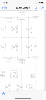
According to the schematic C62,62,65,66 are supposed to be 47uf 16 volt .
There are 100uf 16v caps in the amp now .
wondering should I switch them to 47uf or will the 100uf caps work ?
According to the schematic C62,62,65,66 are supposed to be 47uf 16 volt .
There are 100uf 16v caps in the amp now .
wondering should I switch them to 47uf or will the 100uf caps work ?
Attachments
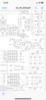

It's likely D52 on the diagram unless there is another diode connected to the collector of the muting transistor.
Ok that’s what I was thinking just wanted to make sure .
On the schematic R56 is a 4.7k the resistor that was in the amp was a 15k .
I think I will leave the 15k resistor it has 5% tolorance and measures 14.81K
Should I replace it ?
On the schematic R56 is a 4.7k the resistor that was in the amp was a 15k .
I think I will leave the 15k resistor it has 5% tolorance and measures 14.81K
Should I replace it ?
- Home
- General Interest
- Car Audio
- Digital Designs Z2HV