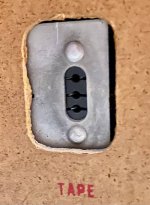
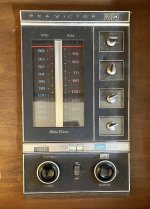
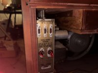
Does anyone know what this chassis plug is? It's mid 60s vintage and is the tape input on an RCA console stereo. Left/right with ground in the center. It's maybe 25-30mm wide.
I vaguely remember these connectors, but haven't seen one in agesand sure don't know what it's called.
Of course the irony is that this RCA console has no RCA connectors. 😛
I vaguely remember these connectors, but haven't seen one in agesand sure don't know what it's called.
Of course the irony is that this RCA console has no RCA connectors. 😛
It would indeed! Where did it go the little rascal?
EDIT: Here it is!
Since I'm an expert on RCA Victor products, I'll say..
That is the old style (prepriatory) connecter they used for their stuff.
Center pin is common ground.
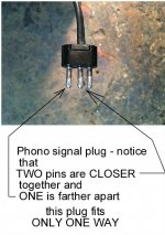
The pin farthest from it (top pin) is right channel...... the remaining pin is left channel.
Look closely, you'll notice that right side pin being farther.
In those consoles, it's used as BOTH an input or output depending on the preamp selector position.
In other words, on "tape" setting, it's a line input.
On phono, am/fm, it's a line output.
They can be removed and replaced with a suitable set of standard RCA jacks.
Last edited:
I have seen it in sewing machine pedals, which control the motor speed.
Try along that line of search.
Or simply change to a newer style if you wish.
Try along that line of search.
Or simply change to a newer style if you wish.
RCA Victor used that proprietary connector to distinguish their own equipment, and naturally to make customers buy "their brand" of accessories like tape recorders, etc.
Just like their other "3 pin" circular style "Total Sound" speaker connectors.
And their record changers used that flat style ceramic cartridge with 3 pins, and again a
proprietary spacing of the mounting screws, to prevent using other brands.
Sneaky marketing tool.
Just like their other "3 pin" circular style "Total Sound" speaker connectors.
And their record changers used that flat style ceramic cartridge with 3 pins, and again a
proprietary spacing of the mounting screws, to prevent using other brands.
Sneaky marketing tool.
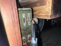
Thanks! Good to know that's is a "real" RCA connector. 🙂 The layout is as you say, with right at the top, the common, in the center, left on the bottom. Interesting that it is both an input and output. This is on a big Finlandia console from from the mid '60s that needs a lot of TLC.
Naresh, yes it does look a lot like those foot pedal connectors on old sewing machines. Maybe that's why it looked familiar to me.
Naresh, yes it does look a lot like those foot pedal connectors on old sewing machines. Maybe that's why it looked familiar to me.
Blasphemy !They can be removed and replaced with a suitable set of standard RCA jacks.
Original is good.
I have to take a look in my boxes, I think that there are some connectors that looks like that, and I didn't know what they were.
Figge
Figge
Yeah it's great - until you can't use it.If it were an easy to find plug I'd make an adapter.
Find some molex pins that will physically fit into the holes, and mount them on a little piece of PCB with the right spacing. Connect RCA cords. I’ve seen plenty of “adapters” that looks like they did exactly this. Sort of the same construction as the pins they plug the cheater cord on to in old radios.
Thanks! Good to know that's is a "real" RCA connector. 🙂 The layout is as you say, with right at the top, the common, in the center, left on the bottom. Interesting that it is both an input and output. This is on a big Finlandia console from from the mid '60s that needs a lot of TLC.
The Finlandia's were one of the top models of that era.
I've had similar monsters in my shop, and yes, they all by now need a complete overhauling.
But they perform quite nicely after servicing.
Does your Finlandia have the record changer with the strobe/speed control?
That was a neat feature back then.
You push down on the speed control knob, a neon lamp then illuminates a little window to show the strobe, then you turn the knob till the dots stand still. (while playing a record).
Also, Pano, snip out the two .047 ceramic disks from the phono input loading in the tuner/pre - they kill the signal and are nonsense to have there.
Nigel - in this case original is bad - I always change those tape jacks with RCA versions to make them compatable with current equipment.
I shave the rivets off the bracket, replace with standard panel mount RCA's right through the oval bracket hole.... done.
You may need to impliment a voltage divider (pair of resistors per ch) to attenuate a cd's signal level though.
Here's a similar TOTL console at my shop 6 years ago that I restored for a customer..
A real monster. - Original MSRP in 1965 = $550
My restoration fee back then = $495
Attachments


Pano, those tuners and amps all require (need I say it) recapping the 'lytics, the changer needs a teardown and flush/re-lube, etc...probably rotten rubber grommets too.
Speakers were matched to the sonics of the system and cabinet, and should remain.
I mentioned previously of the cartridge loading caps and removal.
They're usually ceramic disks (.047) soldered right on the phono input receptacle in the chassis.
Snip 'em out.
By the way, those chassis are a real pain to work on.
The tonearm has a tiny felt pad that literally rides on the record with 10 grams force to clean the grooves, the stylus/cartridge floats behind at around 4 grams.
Novel design and often copied by others.
I've restored so many of those damn things, I can do them blindfolded now.....LOL!
Last edited:
If you need to make a new plug...
put header pins in the socket, and check for continuity.
Then bond them to acrylic or glass epoxy strip with epoxy putty (2 part). You can sand / file the putty for a good looking jack.
put header pins in the socket, and check for continuity.
Then bond them to acrylic or glass epoxy strip with epoxy putty (2 part). You can sand / file the putty for a good looking jack.
Nah, all that messing around trying to recreate a plug for that connector is silly.
Because it's a high impedence circuit, and the grounding is critical.
That plug/jack is lousy, period.
Much easier to convert to RCA style.
A pair of panel mount jacks fit that oval opening perfectly.
Because it's a high impedence circuit, and the grounding is critical.
That plug/jack is lousy, period.
Much easier to convert to RCA style.
A pair of panel mount jacks fit that oval opening perfectly.
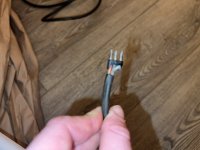
For what it's worth, if anyone is looking for a quick POC on how to make a new connector, I found that XLR connector pins fit just nicely. I repurposed a mic cable I had laying around, but will do the same with a deconstructed single XLR to stereo RCA adapter.
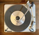
I'm working on modernizing this console to connect to my media server with a phonograph feed in so I can ultimately use it as an Airplay "speaker" and play the TT to my other Airplay speakers. So this is step one as a POC.
I'm working on modernizing this console to connect to my media server with a phonograph feed in so I can ultimately use it as an Airplay "speaker" and play the TT to my other Airplay speakers. So this is step one as a POC.
Attachments

- Home
- Design & Build
- Parts
- Vintage 3 prong connector