I've been running one of the original Cyrus 'pre' amps for many years. Today I found that when the volume level was adjusted one of the motorised pots inside would not settle. It just keeps jittering the motor, like it's constantly seeking a value but can't reach it.
I tried swapping the pots on the PCB for each channel, but the problem channel remained the same, so I do not think the pot itself is the problem, rather the driver circuit.
Does anyone have a schematic? Or know how the volume pot system works?
It seems to me each is a dual pot used for balanced signals. When the level is adjusted I think the circuit seeks a set value on the pots becasue I can see them overshoot slightly and move back again. Or maybe one of the wipers on each dual pot if used for position feedback and the other for the signal?
Volume up, you can hear the pot constantly jittering even when the other one stops at position. Shared album - Simon A - Google Photos
Based on my experience with cyrus units I'd be checking caps in the area.
Much more modern Cyrus cuffer badly with smd (usually) cap fatigue , but you can't rule out through-hole caps on cyrus because the board is constantly upside down (i.e. warm(er) at the top of the cab)
I think you're right with your feedback theory, it's the only way it could work without getting out of synch constantly.
Last edited:
Cyrus Pre HA7L capacitors.
In case anybody needs the info:
2200uf 16v - C503
100uf 16v - C509, c510, c504
10uf 63v - C304, c305, c308, c206, c207 & 2pcs next to those (designations not visible)
2.2uf 50v - C312, c311
22uf 63v - C511, c404, c402, c403, c420, c418, c104, c102, c103, c105, c512, c427, c209, c210
2200uf 35v - C505, c506
47uf 10v Non-polar - C307, c306
I changed all the electrolytic caps but the problem persists.
I did however manage to find a service manual for this!
CYRUS PRE HA7L SM Service Manual download, schematics, eeprom, repair info for electronics experts
I've also uploaded to my google drive here - cyrus_pre_ha7l_sm.pdf - Google Drive
Looking at page 24 we see the schematic for the volume control system. I appreciate some input from you guys on what might be the most likely culprits to cause only one channel potentiometer to not settle? It's on M302 side of things.
IC304 is a dual op-amp used as a compactor and I guess it's unlikely only one half of the duel op-amp has gone bad?
It must be something that is not shared between both channels so I'm looking at T306/T308 and C315.
I'd inspect solder around C315 *and* R368, then replace them.
If those parts are bad there is a ~~1V dead-zone through the transistors.
If those parts are bad there is a ~~1V dead-zone through the transistors.
Attachments
Last edited:
Quick first thoughts...
1/ Desolder the inverting input on both opamps and cross link each to confirm the issue is either before or after that point.
2/ Funny looking pots on the diagram, one gang is log and the other lin is how it looks. But you swapped those over.
3/ Depending on the outcome of '1' are the 2.2uF bipolar caps OK?
.changed all the electrolytic caps but the problem persists
I would have replaced all on a Cyrus of this vintage anyway, it’s eliminated them from the problem, you’ve added value to the amp by ‘renewing’ so don’t feel you’ve wasted your time at all. 🙂
I recently did a Cyrus phono box and 99% of the caps proved badly, badly fatigued and off value by a huge margin.
2/ Funny looking pots on the diagram, one gang is log and the other lin
Attachments
Last edited:
I'm wondering if IC602 (NVRAM) is slightly kaput, it's not unheard of (in general) if there's a step look up table in there for instance
It could be a lot of things... I would approach it by breaking the circuit between digital to the left and analogue to the right and seeing if the issue swaps sides when cross linked.
I've refreshed the solder around those parts but no luck still. I check the SMD cap near each driving transistor and measured in spec. I guess I'll just buy some replacement parts and see if it helps.
It could be a lot of things... I would approach it by breaking the circuit between digital to the left and analogue to the right and seeing if the issue swaps sides when cross linked.
You mean swap the channels for the reference voltage that feeds the motors servo?
I'm wondering if IC602 (NVRAM) is slightly kaput, it's not unheard of (in general) if there's a step look up table in there for instance
It does settle, it just takes ages on one channel. I guess the look up table is not 'stereo' although I don't know for sure because it does channel balance by adjusting each pot to a different value.
You mean swap the channels for the reference voltage that feeds the motors servo?
Yes. Use braid to remove the solder from the pad of the opamp and then just carefully link one pin to the others pad with some fine wire.
Make sure the pins are free and not inadvertently touching the pad.
You can also confirm the digi_gnd is intact at all points marked on the circuit (i.e. all associated areas of digi_gnd are connected together , the end of that resistor ladder on both channels, the motor ground, all the IC301,IC302,IC303 ground are to Digi_gnd
Just to confirm all the digi_gnd's are singing off the same hymm sheet🙂
Just to confirm all the digi_gnd's are singing off the same hymm sheet🙂
Well that's kind of embarrassing.*
I got my scope out, looked at the reference voltage going to the servo and I could see it bouncing around on the channel that was jittering. So I started looking at the smd caps near each of the HC4094 chips then swapped two of the chips around and no luck.
So I realised the analog side was just affecting the signal through the feedback. I started swapping bits around from each channel. Replaced the op-amp, swapped the main transistors, zener diodes, smd caps. Nothing worked.
Finally I did like Mooly suggested and cut the trances between the reference voltage source and the op-amp so I could swap them over. The problem didn't change regardless of that.
At this point I had ruled out everything other than the ressitors!
I went back and swapped the pots over just to be sure and... the problem followed the pot!
*It was a bad pot all this time, probably the linear trace is worn out. I'm not sure why I thought the problem didn't follow the pot when I tried that as the first troubleshooting point.
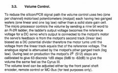
Now I think the only solution is to replace the pots with a digital attenuator and an MC that takes the reference voltage from the Cyrus and sets the digital attenuator chip. Somebody did a similar thing but took the actual signal from the rotary encoder on the front of the pre-amp. I think there is an easier way.
Mission Cyrus Pre - A DIY Digital Volume Control: Status Quo - awiller.de <br> Dont Panic!
I got my scope out, looked at the reference voltage going to the servo and I could see it bouncing around on the channel that was jittering. So I started looking at the smd caps near each of the HC4094 chips then swapped two of the chips around and no luck.
So I realised the analog side was just affecting the signal through the feedback. I started swapping bits around from each channel. Replaced the op-amp, swapped the main transistors, zener diodes, smd caps. Nothing worked.
Finally I did like Mooly suggested and cut the trances between the reference voltage source and the op-amp so I could swap them over. The problem didn't change regardless of that.
At this point I had ruled out everything other than the ressitors!
I went back and swapped the pots over just to be sure and... the problem followed the pot!
*It was a bad pot all this time, probably the linear trace is worn out. I'm not sure why I thought the problem didn't follow the pot when I tried that as the first troubleshooting point.
Now I think the only solution is to replace the pots with a digital attenuator and an MC that takes the reference voltage from the Cyrus and sets the digital attenuator chip. Somebody did a similar thing but took the actual signal from the rotary encoder on the front of the pre-amp. I think there is an easier way.
Mission Cyrus Pre - A DIY Digital Volume Control: Status Quo - awiller.de <br> Dont Panic!
Last edited:
🙂 we've all done it.
I assume you've tried cleaning the pot?
How about trying a cap from the wiper to ground, something like a 22uF for starters. It can only not work.
I assume you've tried cleaning the pot?
How about trying a cap from the wiper to ground, something like a 22uF for starters. It can only not work.

- Home
- Source & Line
- Analog Line Level
- Cyrus Pre HA7L Jiddery Volume?