Hello
Back in the 70s when the Quad 405 power amp was designed, it seems that little boxes were available that amplified the 405 speaker signal output for a headphone output. The box has a switch that either feeds the speaker signal to the headphones or continues the signal to the speakers. The 405 manual has a simple schematic that shows a provisional design.
I thought I would find such a box very easily .. but I have not. Would anyone have an idea where I can find such a thing, preferably as a kit? I am not an audiophile, so I don't need anything very sophisticated.
Many thanks
Welcome to diyAudio 🙂
Any device like you mention will just be a very simple resistive attenuator. Speaker position will link straight through and headphones will be via the attenuator.
It could be made to be either one or the other as selectable, or it could be headphones on all the time and speaker is switchable on and off.
If you can solder you could make one yourself.
Thank you mooly for your thoughts and your welcome.
I figure it is quite simple and I have rudimentary DIY soldering ... but absolutely no electronic engineering experience. I cannot even workout how to describe this box to see schematic on the web. All the words I can think of bring up power amps.
I figure it is quite simple and I have rudimentary DIY soldering ... but absolutely no electronic engineering experience. I cannot even workout how to describe this box to see schematic on the web. All the words I can think of bring up power amps.
I stumbled on this box that looks like it does what I am looking for ... but not really in my price range.
Speaker Amp to Headphone Adapter Box - Listen to headphones from a speaker amp using your existing speaker cables, connect to binding posts
Speaker Amp to Headphone Adapter Box - Listen to headphones from a speaker amp using your existing speaker cables, connect to binding posts
I had a look as well but couldn't find anything 100% suitable, and they were expensive.
I was searching for 'headphone'. 'speaker', 'selector', 'switch'.
Not ideal:
B Blesiya Speaker Selector Switch -Speaker Distribution Controller Box Volume Control, Supports Home Theater Stereo Amplifier Receiver System: Amazon.co.uk: Electronics & Photo
To make one you need a simple box to put it in. These can be a simple or fancy as you choose. Component suppliers have all these parts.
You need the box to be large enough to hold 4 sets of speaker sockets. Speaker in and speaker out for each channel.
You need a headphone socket.
You need a DPDT (double pole double throw) switch to switch the speaker signal.
You need two or four resistors to make the attenuator. These can be soldered direct to the headphone socket.
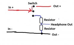
Electrically the circuit is simple. The negative speaker lead just loops through. The switch in the upper position links the speaker feed through unchanged. In the lower position it connects to the attenuator.
The switch (and this applies to ready built as well) must be able to handle the 100 watts output of the Quad. So a decent switch.
The resistors are chosen to suit your headphones, they cost next to nothing and its easy to work out the values. A simpler version just uses the upper resistor alone and not the two.
The main system volume controls the headphone volume, just as it does with speakers.
I was searching for 'headphone'. 'speaker', 'selector', 'switch'.
Not ideal:
B Blesiya Speaker Selector Switch -Speaker Distribution Controller Box Volume Control, Supports Home Theater Stereo Amplifier Receiver System: Amazon.co.uk: Electronics & Photo
To make one you need a simple box to put it in. These can be a simple or fancy as you choose. Component suppliers have all these parts.
You need the box to be large enough to hold 4 sets of speaker sockets. Speaker in and speaker out for each channel.
You need a headphone socket.
You need a DPDT (double pole double throw) switch to switch the speaker signal.
You need two or four resistors to make the attenuator. These can be soldered direct to the headphone socket.
Electrically the circuit is simple. The negative speaker lead just loops through. The switch in the upper position links the speaker feed through unchanged. In the lower position it connects to the attenuator.
The switch (and this applies to ready built as well) must be able to handle the 100 watts output of the Quad. So a decent switch.
The resistors are chosen to suit your headphones, they cost next to nothing and its easy to work out the values. A simpler version just uses the upper resistor alone and not the two.
The main system volume controls the headphone volume, just as it does with speakers.
Attachments
I also found this from your key words:
DIY Audio Electronics from Zynsonix.com: Speaker Amp to Headphone Converter Box
DIY Audio Electronics from Zynsonix.com: Speaker Amp to Headphone Converter Box
That is the sort of thing but these do not seem switchable. I think you want one that allows you to switch freely between speakers and headphones which these do not seem to do.
Thank you so much for your schematic. I certainly have enough to be getting on with.
Concerning the resistors , I am looking at the Sennheiser HD 25 at 70 ohms and 200mv .
Would the resistor thought from the link above, be pertinent ?
"Mills 12 watt non-inductive wirewound resistors as we don't want any induction screwing with the impedance. The Mills are well thought of for good sound quality, so it was an easy choice. I've also used the larger Kiwame 5W carbon film resistors in parallel."
The resistors can be altered to suit you.
I would probably begin by using a 330 ohm 2 watt for the upper one and either a 68 or 100 ohm for the lower one.
(The 330 alone would be quite acceptable without even adding the lower ones)
A metal film type would be ideal. The resistors dissipate little power in use and are only active when headphones are selected.
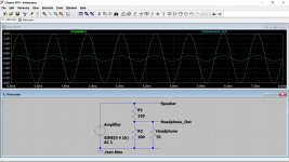
This shows what would typically happen. The amplifier is delivering 1 watt into 8 ohms (that is a typical fairly loud listening level via speakers). A level of 4 volts peak (8 volts peak to peak) corresponds to 1w/8ohm
The headphone voltage and speaker voltage are shown. By altering the resistor value/s you can get whatever level 'feels' right meaning the headphone gives a similar subjective level to the speaker without altering the volume control.
The headphone voltage and speaker voltage are shown. By altering the resistor value/s you can get whatever level 'feels' right meaning the headphone gives a similar subjective level to the speaker without altering the volume control.
Attachments
IMHO :
1) A switch is not necessary as any power amp would be able to drive both at the same time.
__So you can connect the headphone attenuator box in parallel with the speaker at the same time.
2) In the days of the Quad, most headphone outputs were specified with a Zout of 120 ohm.
3) I personally would always want the resistor to Gnd, even if it is high ohmic.
4) The QUAD 405 is specified as +/-40V max output (100W into 8R). No headphone will survive that other than electrostatics. So attenuation is a must.
Most over-ear headphones today are specified for 200mW.
That means for
32R +/-3.6V -21dB from 40V
65R +/-5.1V -18dB
100R +/-6.3V -16dB
300R +/-11V -11dB
To come close to meeting all the above, you can use a potential divider of 330R:220R (slightly different from Mooly).
The headphone will be connected in parallel with the latter.
Both resistors will want to be 2W minimum. I recommend Vishay Dale CPF series.
It is really very simple. No need to pay 300 USD.
Cheers,
Patrick
For noephytes like me, below is an explanation of the issues with this amps and headphones
DIY Audio Electronics from Zynsonix.com: Speaker Amp to Headphone Cable
DIY Audio Electronics from Zynsonix.com: Speaker Amp to Headphone Cable
So why not just pay them to do it for you and sleep well ?
Anything not right, you can get them to rectify.
No need to DIY. Totally foolproof.
Perhaps this is the wrong forum for you ?
Cheers,
Patrick
Anything not right, you can get them to rectify.
No need to DIY. Totally foolproof.
Perhaps this is the wrong forum for you ?
Cheers,
Patrick
You are right to question my legitimacy on such a forum.
Firstly, I figured that it was not too difficult. I have done Arduino projects in the past which needed some very basic soldering skills, so I figured this could be done to the same level. Yes, I have no electronic engineering background, but I have a willingness to learn / appreciate what these skills are. And lastly, sadly, I don't have 299 USD to sink into a box with a switch, some sockets and a couple of resistors. I am sure it is worth it for someone, but not really for me.
Thanks for all your thoughts and advice,
Christopher
So Mooly and I have given you all the information you need.
How would you like to be helped further, other than someone else make it for you ?
Patrick
How would you like to be helped further, other than someone else make it for you ?
Patrick
I think you have given me quite enough to go down to the electronics shop, buy what you suggest, probably get it wrong (because I don't really know what I am doing), break something on the way and learn from it.
But if I did not expect that, it wouldn't be have asked on the forum in the first place. It's all part of the "fun".
But if I did not expect that, it wouldn't be have asked on the forum in the first place. It's all part of the "fun".
Providing you make a few basic tests before connecting it then nothing bad should happen. These would just be simple resistance checks with a meter to confirm that:
1/ The speaker input sockets do not read short circuit across them in either position of the switch.
2/ The speaker + in and speaker + out have continuity when in speaker position. In other words the box passes the speaker feed through correctly.
3/ The headphone socket 'live' pins read at least 330 ohm or open circuit (or whatever resistor value is decided on) to speaker + in and speaker + out for both switch positions.
And it will work 🙂
If you are using standard 6.3mm TRS for your phones, you can actually put all 4 CPF2 resistors inside a Neutrik NJ3FC6 (see attached).
Then 4 cables out to the QUAD 405, which I guess have a common Gnd for both channels.
If the Quad does not have a common Gnd, then you cannot use TRS, but would need to have a headphone that can take balanced cables.
Patrick
.
Then 4 cables out to the QUAD 405, which I guess have a common Gnd for both channels.
If the Quad does not have a common Gnd, then you cannot use TRS, but would need to have a headphone that can take balanced cables.
Patrick
.
Attachments
- Home
- Amplifiers
- Headphone Systems
- Headphone amp for QUAD 405 amp