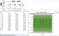
I want to have dedicated power supplies for the driver vs. output tubes. The driver tube would have a Ua of 120-150Vdc. Can the mains voltage be used directly, without a power transformer, for the driver tube using the psud schematic below? This is just for the driver tube which requires 120-150Vdc at the plate.
Attachments
Yes, you need a proper power transformer for safety. (And to stay within the forum safety rules.)
The first rule is safety.
A transformer is needed to Isolate you from any connection to the mains.
Also the circuit you show would not work as the full wave rectifier with two diodes needs a centre tap to function. Note the transformer secondary has 3 connections in the diagram.
A transformer is needed to Isolate you from any connection to the mains.
Also the circuit you show would not work as the full wave rectifier with two diodes needs a centre tap to function. Note the transformer secondary has 3 connections in the diagram.
While it IS possible, it's a safety no-no as others have said, and it won't work except as a half wave rectified supply. I wouldn't directly power anything that plugs into something else but no transformer is needed for a light bulb, for example, and there is no transformer in a heater or my stove, either...
I've considered the idea of making a tube amp that ran directly from the line with the isolation provided by input and output transformers but it's still dangerous and I'm not going to do it.
For less than 20$USD just use a Triad N-68X...
I've considered the idea of making a tube amp that ran directly from the line with the isolation provided by input and output transformers but it's still dangerous and I'm not going to do it.
For less than 20$USD just use a Triad N-68X...
Last edited:
I am glad I asked. Probably the best (most naive) question, with even better answers. Case closed.
Kodabmx: interesting idea. on the existing PT, there is a 70V tap that is unused. hmm. now you have me thinking.
I am glad I asked. Probably the best (most naive) question, with even better answers. Case closed.
If seperating the stages with seperate PS's is that important or beneficial, then spending a couple of bucks on a salvage 120v/6v wall wart transmormer would shurely do the job, hooked backward onto the heater winding. There ought to be a box full to pick through at the GW.
Last edited:
Like this ?Kodabmx: interesting idea. on the existing PT, there is a 70V tap that is unused. hmm. now you have me thinking.
Mona
Attachments
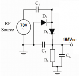
Even better! 🙂 And it's not hard to drop 50V @ 25mA... 2k/3W into 220uF as RC filter will make it pretty quiet, too. Or use 1k5 and a VR150 regulator 🙂
Last edited:
That is a slick solution, but banpuku says it is a 70v tap not separate winding. So does not quite meet the original ask in post #1 for a dedicated supply.
Given that this is a 70V tap (not separate winding), if the filtering/rectification is properly executed, this should work OK. The intent behind the original idea was to eliminate the need for a large dropping resistor when using the same B+ as the output tube.
What would the use be of getting rid of a large dropping resistor (which gives good filtering if combined with a good and large enough capacitor), but in exchange getting an extra rectifier/smoothing circuit? Do you expect a sonic improvement by doing so?
Given that this is a 70V tap (not separate winding), if the filtering/rectification is properly executed, this should work OK. The intent behind the original idea was to eliminate the need for a large dropping resistor when using the same B+ as the output tube.
There's too much resistorphobia being spread across hobby boards. If the PS is planned for enough power margin, then there will be plenty of energy available to drive input amps with no detrimental affects under the max load. That's called designing. If you under engineer, you get what you pay for. Resistors are not evil. Electrolytics are not evil. Simplicity that works is the best plan. So it's not a unique design.. whoopty.
Achieved by using 10X the complication 20X the price of a dropping resistor, which to boot provides *superior* supply voltage, since you start with an already filtered, low hum supply and add at least one extra RC node, two if you wish, end result will be very very clean.The intent behind the original idea was to eliminate the need for a large dropping resistor when using the same B+ as the output tube.
Maybe he just doesn’t want to deal with extra heat. In order to filter a half wave aux supply well without a large dropping resistor he’ll need a *choke* which is much more expensive than a resistor. But cooler for sure. I’ve resorted to using center tapped and stacked supplies, to reduce the dissipation in dropping resistors and voltage regulator mosfets and reduce the required voltage rating on caps. I don’t like the idea of dropping 200-400 volts (times the current) as heat if there is a viable alternative.
- Home
- Amplifiers
- Tubes / Valves
- No Power Transformer for 150V Ua Driver