Hello, I'm planning to build a single ended amplifier (triode or linear) based on a pair of russian 6P3S tubes. I already made the wooden/iron sheet chassis for it and now a guy that I know suggested me a scheme with two 6n2p in SRPP pe channel as driver tubes. I wonder if that can be OK, some other schemes around show also a single tube with high mu (ECC85, 12AX7, ecc.) shared with both or ECC82 - ECC88 in single or common cathode configuration too.
Another question, a 2.5k output transformer can be suitable with these russian ones? I know a 3.5-4k should be the optimal, but I tried managing loadlines and it seemed to be right a Rk=400R at 300V B+ maybe adding some feedback.
Thanks
Another question, a 2.5k output transformer can be suitable with these russian ones? I know a 3.5-4k should be the optimal, but I tried managing loadlines and it seemed to be right a Rk=400R at 300V B+ maybe adding some feedback.
Thanks
If you mean 2 pre-stages per channel with in each stage one 6N2P srpp connected, than you would get way too much gain (about 50 x 50 = 2500). If you mean one 6N2P srpp connected per channel than the gain would about 50 so that would leave some room for NFB if you would desire.
I leave it to others to comment on whether or not a 6N2P srpp driving a 6P3S triode connected is a good choice sound- or otherwise.
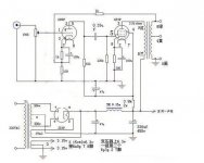
A primary of 2.5K for the 6P3S triode connected seems very low to me (it is even less than 2 x the plate resistance in triode mode). But here are a schematic in which a primary of 2.5 K is being used and the datasheet of the OPT (it's realy being used as 2.5K/8 Ohm).
I leave it to others to comment on whether or not a 6N2P srpp driving a 6P3S triode connected is a good choice sound- or otherwise.
A primary of 2.5K for the 6P3S triode connected seems very low to me (it is even less than 2 x the plate resistance in triode mode). But here are a schematic in which a primary of 2.5 K is being used and the datasheet of the OPT (it's realy being used as 2.5K/8 Ohm).
Attachments
Last edited:
Thanks for the files, although in chinese I noticed the various diagrams and the one where the 2.5 OT is employed.
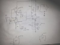
I meant one 6n2p per channel, as you can see from the attached schematic below.
Unfortuntely the OT I own is this, I know its impedance is barely matched with the 6P3S (maybe it should be better with 2A3 or similar).
I meant one 6n2p per channel, as you can see from the attached schematic below.
Unfortuntely the OT I own is this, I know its impedance is barely matched with the 6P3S (maybe it should be better with 2A3 or similar).
Attachments
Data sheet says 2.5K load for 250V plate and screen, idle at 72 mA. Some negative feedback required to reduce distortion and lower output impedance.
I suppose you are talking about the tube running as tetrode, in this case theoretically Rl is ~ 1/6-1/10 the tube Rp (that is 2500-4200Ω) . Or with the standard formula, 250^2/20.5 ~3000Ω. Of course a certain amount of feedback is required to have an acceptable distortion.
I come to say that with these OT it's not possible to run the amplifier in triode mode, maybe in U.L. with feedback, but I have to estimate if thus the power output were too low.
I come to say that with these OT it's not possible to run the amplifier in triode mode, maybe in U.L. with feedback, but I have to estimate if thus the power output were too low.
Yes you can get about 7W in pentode mode and 3.5k OT. I like 6SN7/6N8P driver sound and I can almost hear the same sound signature with other output tube or topology, either cascode 6SN7 or single section 6SL7 or similar can drive it to full power. You notice the screen supply voltage has been lower from plate supply(315) with zener or resistor by about 100V to 190V.
6N8P and 6P3P Single Ended Stereo Amplifier
6n9p+6p3p Tube Amplifier SRK 10|amplifier connection|amplifier modulamplifier dts - AliExpress
6N8P and 6P3P Single Ended Stereo Amplifier
6n9p+6p3p Tube Amplifier SRK 10|amplifier connection|amplifier modulamplifier dts - AliExpress
Attachments

Last edited:
Cathode feedback from 8 Ohm winding gives 2.8K effective load, using 16 Ohms for feedback gives 2900. Return the cathode bypass to the secondary instead of ground (opposite end grounded, properly phased, of course). This doesn't give much feedback, maybe 2 dB.
The second circuit seems to be more interesting, the screen of the 6p3p is well regulated with a series of zeners even though I'd have put maybe a MKP capacitor to ground.
The problems I'd like to use some tubes I already have. Russian ones I have just three kinds, 6p1 6n2p and (6p3s as p.t.) or alternatively ecc82, ecc88, ecc85, 6cg7...
I suspect then that the pair of OT I bought, rated by the seller for EL34, 6L6, ecc, are in reality suitable for building a guitar amp where tubes run "tight at the neck" and no HIFI requirements are needed.
From what I recall 6P3S wants OPT to be about 5k or 6k in Triode, maybe 4k in tetrode mode, similar to 6P6S but higher ratings.
As for the driver, I have been looking at this, and although I have yet to try, I have considered: 6N3P, 6N5P, ECC88.
I reckon 6N2P might be a bit weak, but that is only an assertion
As for the driver, I have been looking at this, and although I have yet to try, I have considered: 6N3P, 6N5P, ECC88.
I reckon 6N2P might be a bit weak, but that is only an assertion
I think the input capacitance of a 6L6 (6P3S) in triode is about 100pF (I might be guessing high, but better that than guessing too low).
The idea is that you want the driver stage to be able to sink enough current to avoid slew limiting on loud high frequency transients with the amp cranked.
According to my calculations, if your 6P3S-triode is biased to -35Vg1, and you want to be able to drive that 35V peak up to 100kHz (overkill, I know, but...) then the driver stage will need to sink 2.2mA into the input capacitance.
In my estimation, a 6N2P would be kind of marginal in that position, but it would probably work well enough in real life because actual music doesn't have high frequency content at full scale (most of the energy is in the low midrange). However, I think it's good practice to design with lots of headroom, so I'd prefer to see a driver tube with Ip of 4mA or more. You could always use a 6N2P with a 6N8S, 6N3P or ECC88 cathode follower or a MOSFET source follower after it.
Some people like a single triode driver stage like a 6S45P or a triode-wired 6J9P or 6J52P, but that gets into RF tubes that tend to vary widely and can be microphonic.
Thanks for the suggestion, indeed around thera are several schematics based on cathode follower in the driver stage as you say and can bring some sonic improvements as you say. Anyway since the OT's have 50% ultralinear taps I think I use them instead of mere triode.
The trouble is how to use the current OTs beacuse of their fail low impedance (2.5k), setting too down for these tubes. They are 15W (about 1.5kg each) and well made for throw them away (the factory is ES.CO. electronic surplus)and abort the project.
Although not in the better way, my idea is to swap my 8ohm speaker into the 4ohm secondary tap, so to have a secondary reflected impedance of about 4800ohms. Of course I'll lose a little of mid-high frequency and get some lack of power but I can try and see.
The trouble is how to use the current OTs beacuse of their fail low impedance (2.5k), setting too down for these tubes.
These are single-ended OPTs, correct? A 2.5k ohm primary would be about right for 2A3 or 300B, and would also be just about right for EL34 in triode, especially if used more on the low plate voltage/high plate current side of things, like 325V plate-cathode, 70mA plate current. You'd get less power that way, but since you'll be going with ultralinear using the screen tap, you should get a few watts.
However, for 6P3S/6L6GB, that 2.5k primary is probably too low. According to the old tube data sheets, 6L6-triode with Vp = 250V and Ip = 40mA has rp of 1700 ohms. Maybe if you use the 4 ohm secondary tap...
Thanks for the suggestion, indeed around thera are several schematics based on cathode follower in the driver stage as you say and can bring some sonic improvements as you say. Anyway since the OT's have 50% ultralinear taps I think I use them instead of mere triode.
The trouble is how to use the current OTs beacuse of their fail low impedance (2.5k), setting too down for these tubes. They are 15W (about 1.5kg each) and well made for throw them away (the factory is ES.CO. electronic surplus)and abort the project.
Although not in the better way, my idea is to swap my 8ohm speaker into the 4ohm secondary tap, so to have a secondary reflected impedance of about 4800ohms. Of course I'll lose a little of mid-high frequency and get some lack of power but I can try and see.
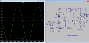
You can use a lower OT Z of 2.5k with additional modifications, but preferable use a tube with high dissipation say 30W 6L6GC/6LGT :
1. Increase Schade or shunt feedback (Change R4 from 1.5Meg to 1Meg)
2. Add Cathode feedback (wire output tube cathode to output instead of ground). Doing this reversed the output phase and you can not use NFB but that is ok as I modified the driver to use more local feedback instead to reduce distortion. You can read more about Schade feedback in this thread:
Schade Feedback
I can post the simulation file is you want it.
Attachments
Last edited:
I didn't consider yet about a cascode circuit, but as shown in your graph it seems to work well with 6SN7, 9W is a good power notwithstandig the feedback.
It reminds me in someway the Abdellah/Gendrano schematic, except the driver stage.
Clearly a higher voltage is needed, but I have to see if my OT's are enough for this and the power tubes 6L6GC 30W. I think in that case with almost 100mA (87+10) of current flowing through the tube a 20W OT would be better than actual 15W.
I noticed also a hundred pF input cap for compensating Miller's effect and the use of a led in the driver cathode (lower noise I guess), so I'll put "in the to-do list" this circuit...
I found another schematic that could work maybe for my needs.
It employs two paralleld tubes in the driver stage (12AX7 ≈ 6N2P-EV) and contains variable NFB. In such these operating conditions the 2.5k OT seems it can be ok, for the listed range of tubes.
https://www.audiofaidate.org/uploaded/plovati/ace8W_chimeralabs.jpg
It employs two paralleld tubes in the driver stage (12AX7 ≈ 6N2P-EV) and contains variable NFB. In such these operating conditions the 2.5k OT seems it can be ok, for the listed range of tubes.
https://www.audiofaidate.org/uploaded/plovati/ace8W_chimeralabs.jpg
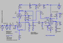
I think that in the schematic of Mona the current through the 6SN7 has to be 1.53 mA, so the indicated 1.81 mA must be a 'left over' from the schematic of Koonw.
I(R5) = V(R5) / R5 = 2.454 / 470 = 5.22 mA
I(R1 + R31) = V(R1 + R31) / (R1 + R31) = (255.406 – 2.454) / 1330000 = 0.19 mA
I(R4) = V(R4) / R4 = (353.431 – 2.454) / 100000 = 3.5 mA
I(6SN7) = I(R5) – I(R1 + R31) – I(R4) = 5.22 – 0.19 – 3.5 = 1.53 mA
This outcome fits with
I(R2) = I(6SN7) + I(R1 + R31) = 1.53 + 0.19 = 1.72 mA
and
I(R2) = V(R2) / R2 = (371.87 – 255.406) / 68000 = 1.71 mA
- Home
- Amplifiers
- Tubes / Valves
- Driver stage for 6p3s SE amplifier