Hello,
I got an Atoll PH100 phono stage and was wondering if upgrading these caps will get me some improvements:
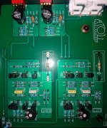
-100 pf input ceramic disk caps (these are switchable and when on noise floor increases noticiably)
-220 uf electrolytic caps
-4.7 nf yellow caps
-15 nf white caps
Are the yellow-white caps polyester?
I have compared it to my Rothwell Simplex. Bear in mind the Atoll is brand new, just a few hours of duty and the Simplex is fully burnt in! The Atoll sounds very good but the Simplex has a bit more weight on lower mid frequencies (maybe between 100-400 hz) wich gives a fuller, more sculpted central image... I wonder if the Atoll will get there when burnt in or the type of caps may have something to do.
By the way, do you know what the 2 variable resistors at the bottom of the picture do? I tweaked one and couldn't notice any difference... but I couldn't listen from the listening position while moving the pot, so maybe that's why.
Thanks
I got an Atoll PH100 phono stage and was wondering if upgrading these caps will get me some improvements:
-100 pf input ceramic disk caps (these are switchable and when on noise floor increases noticiably)
-220 uf electrolytic caps
-4.7 nf yellow caps
-15 nf white caps
Are the yellow-white caps polyester?
I have compared it to my Rothwell Simplex. Bear in mind the Atoll is brand new, just a few hours of duty and the Simplex is fully burnt in! The Atoll sounds very good but the Simplex has a bit more weight on lower mid frequencies (maybe between 100-400 hz) wich gives a fuller, more sculpted central image... I wonder if the Atoll will get there when burnt in or the type of caps may have something to do.
By the way, do you know what the 2 variable resistors at the bottom of the picture do? I tweaked one and couldn't notice any difference... but I couldn't listen from the listening position while moving the pot, so maybe that's why.
Thanks
Attachments
Hello,
By the way, do you know what the 2 variable resistors at the bottom of the picture do? I tweaked one and couldn't notice any difference...
It seems like a good idea to begin this by drawing up a circuit. It won't take you more than an hour, likely less.
My guess is the trim pots are there to adjust the DC nul at output. Easy enough to test.
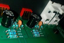
The riaa caps seem smallish to be polyprop but best is to desolder and test them with a hair dryer. Polyprop has negative TC and polyester positive.
The tolerance of these caps is important which makes it quite hard to upgrade them. A circuit drawn in a simulator can show how important exactly.
The ceramics are an odd choice for input loading a MM cartridge but will have no effect if switched out of circuit. A silver mica would be a better type of capacitor for this position. The 220µF electros may be used for feedback decoupling or possibly input coupling. Regardless of application, measure the voltage across them. If it is a fraction of a volt replace them with audio grade bipolar electros, such as Nichicon Muse, which will have lower distortion. I don't know what type of film the other two capacitors are. Wima MKP4 are often considered a good choice for this application (RIAA filter). The trimpots may be for bias, DC offset of input or output. Don't fiddle with them if you don't know what they do. Oops, too late! If its for the input you may inadvertently put current through a moving coil cartridge. If it's bias you may affect distortion levels or maximum output capability. Hopefully someone smarter than me will chip in.
The 220µF electros may be used for feedback decoupling or possibly input coupling.
99% it's for nfb decoupling. This explains its location by the mm/mc switch. The corresponding resistors must be right next to it.
Which makes it a very important cap as far as sound is concerned.
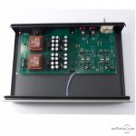
The OP for some reason has included pics from two different units. Curiously, the designer kept a placeholder for an output film cap even after they moved to a double sided pcb. Perhaps the dc trimming did not inspire long term confidence 🙂
Last edited:
Thanks everybody for the answers!
Analog_sa, unfortunaltely my knowledge of electronics doesn't go much far away than soldering/basic multimeter testing, I'm unable to draw a circuit and interpret anything there. The last photo I uploaded is from the web so you see the whole unit, the left side with the transformer and bunch of caps is actually covered by a metal compartment.
Johnmath, after fiddling with the trimpot i left it just as it was before just in case! Won't do it again 😱. The preamp sounds good without the input loading ceramics but I will change them in case they're needed at some point... About the film caps I was also thinking about getting red Wimas or similar and see what happens
About the non polar caps, I actually have a couple of unused BIpolar Nichicons KZ Muse 220uf 25v lying around... is it ok to use 'em then? Isn't there a reason why they used non-polars in the first place...?
Thanks
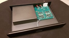
Edit: I've just realised the unit on this web pic I'm attachin comes with bipolar caps 😕
Analog_sa, unfortunaltely my knowledge of electronics doesn't go much far away than soldering/basic multimeter testing, I'm unable to draw a circuit and interpret anything there. The last photo I uploaded is from the web so you see the whole unit, the left side with the transformer and bunch of caps is actually covered by a metal compartment.
Johnmath, after fiddling with the trimpot i left it just as it was before just in case! Won't do it again 😱. The preamp sounds good without the input loading ceramics but I will change them in case they're needed at some point... About the film caps I was also thinking about getting red Wimas or similar and see what happens
About the non polar caps, I actually have a couple of unused BIpolar Nichicons KZ Muse 220uf 25v lying around... is it ok to use 'em then? Isn't there a reason why they used non-polars in the first place...?
Thanks
Edit: I've just realised the unit on this web pic I'm attachin comes with bipolar caps 😕
Attachments
Last edited:
Polarised caps are cheaper and smaller. Some people think that a bipolar, being more or less two back to back polar caps, will have a greater deleterious effect on sound, but actually the opposite is true; bipolars have lower distortion. I guess the non-linear behaviours of the two sections back to back cancel out.About the non polar caps, I actually have a couple of unused BIpolar Nichicons KZ Muse 220uf 25v lying around... is it ok to use 'em then? Isn't there a reason why they used non-polars in the first place...?
Edit: I've just realised the unit on this web pic I'm attachin comes with bipolar caps 😕
A polar cap needs a polarising charge, so will slowly degrade if there is no DC bias across it. Some designers ensure the rails come up unequally at turn-on so that the coupling caps get a pulse of bias to maintain the capacitor's performance over time; I suspect many more designer are oblivious to the issue.
Thanks for the explanation,
I've just noticed I confused things, when I said bipolar I meant polarised, the Nichicon Muse caps I have lying around are polarised.
All the photos of units i've seen online come with polarised caps... it seems mine is the odd one with non-polar caps
I've just noticed I confused things, when I said bipolar I meant polarised, the Nichicon Muse caps I have lying around are polarised.
All the photos of units i've seen online come with polarised caps... it seems mine is the odd one with non-polar caps
I wasn't aware that Muse came in polarised versions. I assume they were all bipolar.
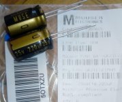
Nichicon MUSE Bi-polarized acoustic series. Suited for audio signal circuits.
Nichicon MUSE Bi-polarized acoustic series. Suited for audio signal circuits.
I also did not realize that Nichicon 'Muse' series were made polarized as well. Nonetheless, the Nichicon ES series are the ones to get---they are bipolar, and measure with extremely low distortion.
If you buy the small RIAA caps from certain places, like Parts Connexion, they will match them for a small,
very reasonable fee. Much cheaper than buying several parts to try to get two that closely match,
which is not necessarily even going to happen.
very reasonable fee. Much cheaper than buying several parts to try to get two that closely match,
which is not necessarily even going to happen.
Last edited:
- Home
- Source & Line
- Analogue Source
- Is it worth Improving phono stage caps? Atoll PH100