Hi folks,
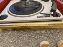
So I have this turntable & speaker system, it's very old and seems to be very un-documented online. Thankfully the internal circuit is extremely simple with a mains transformer, a metal 2 prong rectifier, an EL84 tube, a 2x32uf smoothing cap and an audio transformer. Additionally a couple resistors and small caps.
I've fully serviced the turntable, stripping down all the mechanics and cleaning them - it runs like a dream. I've replaced the metal rectifier with a 1n4007 diode + a 100ohm resistor. The smoothing cap is in-spec so I left it, as are the 2 resistors and small caps found elsewhere. The EL84 seems fine, but I've got another on hand too - have tested it with both with the same results.
Voltages are good, turntable is good, sound is good - what's the problem?
Well, the mains transformer makes a REALLY loud buzzing noise. I've never heard a transformer make this kind of noise before, it sounds like a ratchet constantly spinning. It's loud enough to make the deck basically unusable for listening to music. Having physically detached the transformer and moved it away from the rest of the deck while keeping it connected by wires, i can confirm that the noise is 100% definitely coming from it and not the rest of the circuit or the speaker.
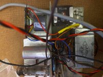
Does anyone have any suggestions here? I cannot find any information about this transformer online, or schematics for the deck, but the transformer seems to be stepping mains voltage up to about 330v for the EL84. I presume I have no choice but to replace it, but I have no idea how to gather the information I'd need to do this correctly. It has 4 wires on its secondary, two going to the EL84, one going to the rectifier diode (which then goes to the smoothing cap) and one going to the metal chassis. If there's any other solution available please let me know.
I can say one thing - the noise isn't present when you first turn it on. It comes on as soon as the valve starts warmly glowing, after about 10-15 seconds.
I'm testing the device through a dim-bulb tester with a 70w bulb, which barely lights up at all. The buzz happens when plugged directly into the wall too.
R
So I have this turntable & speaker system, it's very old and seems to be very un-documented online. Thankfully the internal circuit is extremely simple with a mains transformer, a metal 2 prong rectifier, an EL84 tube, a 2x32uf smoothing cap and an audio transformer. Additionally a couple resistors and small caps.
I've fully serviced the turntable, stripping down all the mechanics and cleaning them - it runs like a dream. I've replaced the metal rectifier with a 1n4007 diode + a 100ohm resistor. The smoothing cap is in-spec so I left it, as are the 2 resistors and small caps found elsewhere. The EL84 seems fine, but I've got another on hand too - have tested it with both with the same results.
Voltages are good, turntable is good, sound is good - what's the problem?
Well, the mains transformer makes a REALLY loud buzzing noise. I've never heard a transformer make this kind of noise before, it sounds like a ratchet constantly spinning. It's loud enough to make the deck basically unusable for listening to music. Having physically detached the transformer and moved it away from the rest of the deck while keeping it connected by wires, i can confirm that the noise is 100% definitely coming from it and not the rest of the circuit or the speaker.
Does anyone have any suggestions here? I cannot find any information about this transformer online, or schematics for the deck, but the transformer seems to be stepping mains voltage up to about 330v for the EL84. I presume I have no choice but to replace it, but I have no idea how to gather the information I'd need to do this correctly. It has 4 wires on its secondary, two going to the EL84, one going to the rectifier diode (which then goes to the smoothing cap) and one going to the metal chassis. If there's any other solution available please let me know.
I can say one thing - the noise isn't present when you first turn it on. It comes on as soon as the valve starts warmly glowing, after about 10-15 seconds.
I'm testing the device through a dim-bulb tester with a 70w bulb, which barely lights up at all. The buzz happens when plugged directly into the wall too.
R
Me thinks it's the smoothing caps. If the rectifier consists in only One diode, It Is likely that the caps have to do a lot of job.
Well, if It buzzes it's another thing. A bad cap can leak to ground thus making an abnormal suction of current from the trafo, which would make It buzz
One way rectification puts unbalanced load on the transformer.
Replace with a bridge rectifier and adapt the resistor for equal
voltage. The initial voltage before heat up may be too high for
the existing caps though.
Replace with a bridge rectifier and adapt the resistor for equal
voltage. The initial voltage before heat up may be too high for
the existing caps though.
One way rectification puts unbalanced load on the transformer.
Replace with a bridge rectifier and adapt the resistor for equal
voltage. The initial voltage before heat up may be too high for
the existing caps though.
I'm not sure that I trust my understanding of the circuit well enough to do this...
well, look at the pulses...
Rectifier - Wikipedia
If what you have described is right ( the transformer has one output to ground and the other to the single rectifier diode ) then the capacitor has to do the job of making that pulses a straight line ( perfect DC ...)
Rectifier - Wikipedia
If what you have described is right ( the transformer has one output to ground and the other to the single rectifier diode ) then the capacitor has to do the job of making that pulses a straight line ( perfect DC ...)
well, look at the pulses...
Rectifier - Wikipedia
If what you have described is right ( the transformer has one output to ground and the other to the single rectifier diode ) then the capacitor has to do the job of making that pulses a straight line ( perfect DC ...)
Sorry - I do understand this, and have already followed your advice and ordered a replacement smoothing cap. Will follow up when it arrives and let you know if it solves the problem. Though I mentioned the transformer actually has 4 outputs, one to ground, one to diode, two to EL84.
The thing I said I didn't understand well enough was how to convert the circuit from one-way rectification to a bridge, as recommended by 'as_audio'
In the meantime the mains voltage has probably increased,
which may add to the problem. I wonder why this is a one
tube amp without any small signal tube (it must be a capable
pick up). You would expect 250 Vdc for a single EL 84 usually.
Why do you not publish some pictures to assist the forum in
helping you ?
which may add to the problem. I wonder why this is a one
tube amp without any small signal tube (it must be a capable
pick up). You would expect 250 Vdc for a single EL 84 usually.
Why do you not publish some pictures to assist the forum in
helping you ?
Why do you not publish some pictures to assist the forum in
helping you ?
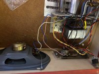
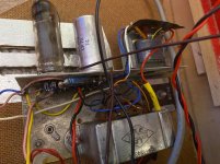
Here! Thank you.
Note: The metal rectifier is still there, but it isn't connected anymore. The 1n4007 is under the yellow heatshrink.
Attachments
-
 216072788_335791708165541_4694370643637883104_n.jpg181.9 KB · Views: 255
 -
 213524365_898933430723833_5831035558626659271_n.jpg167.8 KB · Views: 276
 -
 210782331_354357056300594_6762409759266707257_n.jpg143.5 KB · Views: 266
 -
 215984514_514386516335482_7730620540370881174_n.jpg146.7 KB · Views: 267
 -
 214018971_360814668891600_8382020742098891997_n.jpg142 KB · Views: 257
 -
 216036020_196503685668695_1789888466976701614_n.jpg153.1 KB · Views: 125
 -
 213715467_1445377895827807_3567546911608916064_n.jpg215.9 KB · Views: 118
The transformer surely suffers from increased mains voltage.
In order to check this measure the filament voltage.
The diode rectifier resistor should be increased or an adequate
light bulb used to decrease the mains input.
The transformer should be impregnated at the local winder and
mounted on rubber.
In order to check this measure the filament voltage.
The diode rectifier resistor should be increased or an adequate
light bulb used to decrease the mains input.
The transformer should be impregnated at the local winder and
mounted on rubber.
The transformer surely suffers from increased mains voltage.
In order to check this measure the filament voltage.
The diode rectifier resistor should be increased or an adequate
light bulb used to decrease the mains input.
The transformer should be impregnated at the local winder and
mounted on rubber.
All understood, with the exception of 'impregnated at the local winder' - what does this mean?
Note - the buzzing was happening prior to the replacement of the metal rectifier, does that change anything in your view regarding the rectifier resistor?
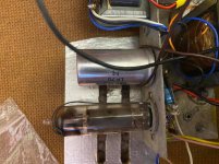
Hi, are you sure that the old rectifier has only two prongs? It Is too big to house Just One diode inside. With One diode you obtain half wave rectification, with a bridge (4 diodes) you get full wave rectification.
1 - a vacuum treatment of the transformer in specialised varnish
This doesn't sound like something I can do...
Hi, are you sure that the old rectifier has only two prongs? It Is too big to house Just One diode inside. With One diode you obtain half wave rectification, with a bridge (4 diodes) you get full wave rectification.
Absolutely certain, without a shadow of a doubt. The device was definitely built for half-wave rectification.
... which means 'built in economy'!
I would simply connect the two AC Wires to a FW bridge rectifier (three more 1N4007) and see what happens..
I would simply connect the two AC Wires to a FW bridge rectifier (three more 1N4007) and see what happens..
I would simply connect the two AC Wires to a FW bridge rectifier (three more 1N4007) and see what happens..
But there are 4 wires coming off the transformer... So leave the two connected to the EL84 and connect the diode and ground ones to the new bridge, then plus to the current cathode end and - to ground?
This doesn't sound like something I can do...
" .. at the local winder. "
Something like that-...leave the HT (Heather) Wires to the el84. Remove the diode, lift the other wire from the chassis, use Four diodes followed by CRC smoothing
- Home
- Amplifiers
- Tubes / Valves
- Elizabethan Pop Ten restoration